Method for preparing carbon nanotube or carbon microtube

a carbon nanotube and microtube technology, applied in the field of carbon nanotube materials, can solve the problems of low yield, complex process, high cost, etc., and achieve the effect of low yield and high production cos

Active Publication Date: 2014-01-30
LIU JIANHONG +2
View PDF1 Cites 9 Cited by
  • Summary
  • Abstract
  • Description
  • Claims
  • Application Information

AI Technical Summary

Benefits of technology

[0008]In view of the above-described problems, it is one objective of the invention to provide a method for preparing a carbon nanotube or a carbon microtube for purposes of solving problems including complicated preparing process, high production costs, and low yield in the prior art.
[0035]The invention provides a method for preparing a carbon nanotube or a carbon microtube, by which carbon tube materials and various doping element modified carbon nanotube or carbon microtube materials are obtained. Not only does the carbon tube have particular appearances, high conductivity, and specific capacity, but also the cycle performance is highly improved. The method is superior in simple process and device, low production costs, high yield, high purification and excellent appearance of the carbon tube. As the LPAN contains a large number of functional groups and is a liquid precursor, by doping modification, the LPAN is evenly mixed and tightly combined with the doping agent to form a carbon nanotube comprising a center filled with nodular doping agent, and a bamboo-shaped carbon nanotube / microtube having a surface attached with doping agent particles.

Problems solved by technology

Typical preparation methods for the carbon nanotubes include an arc discharge method, laser ablation method, chemical vapor deposition method (hydrocarbon gas pyrolysis), solid phase pyrolysis, glow discharge method, combustion gas method, and polymerization synthesis, all of which have a complex process, high costs, and low yield.

Method used


Image

  • Method for preparing carbon nanotube or carbon microtube
  • Method for preparing carbon nanotube or carbon microtube
  • Method for preparing carbon nanotube or carbon microtube

Examples


example 1

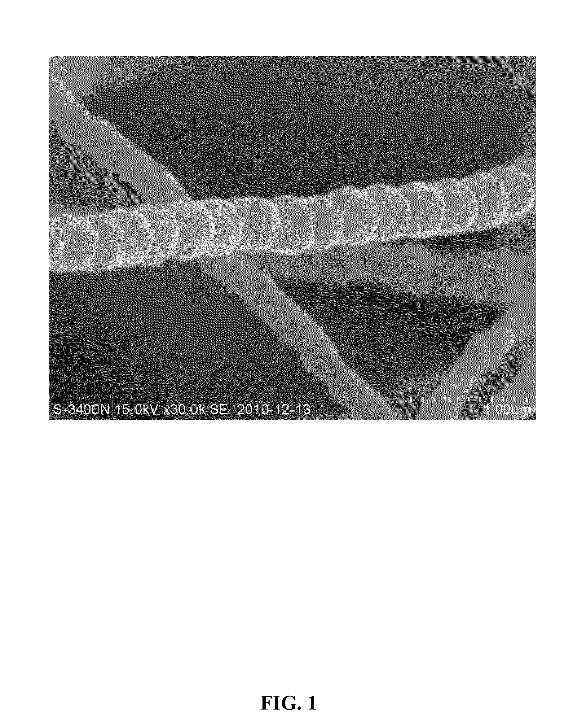
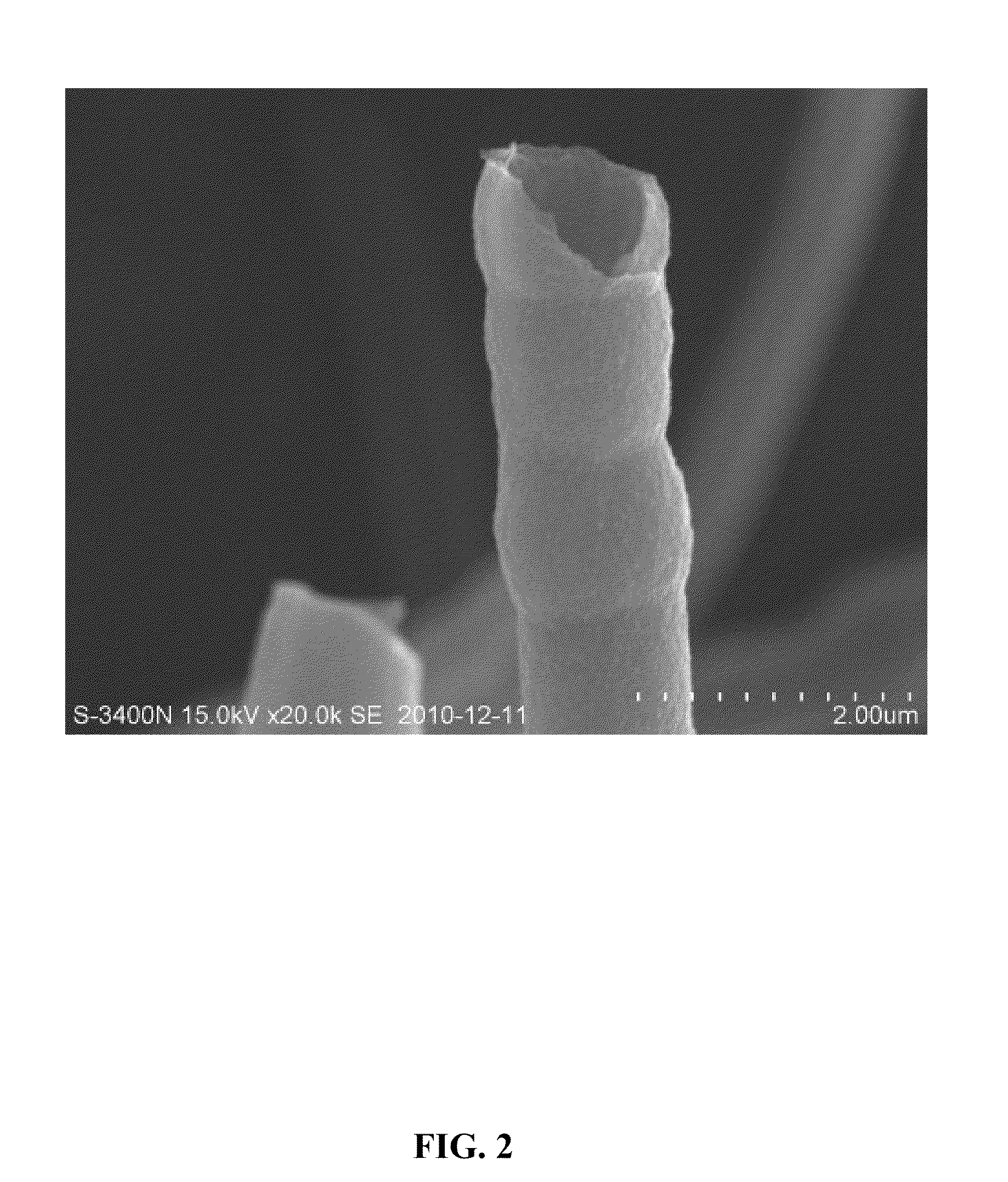
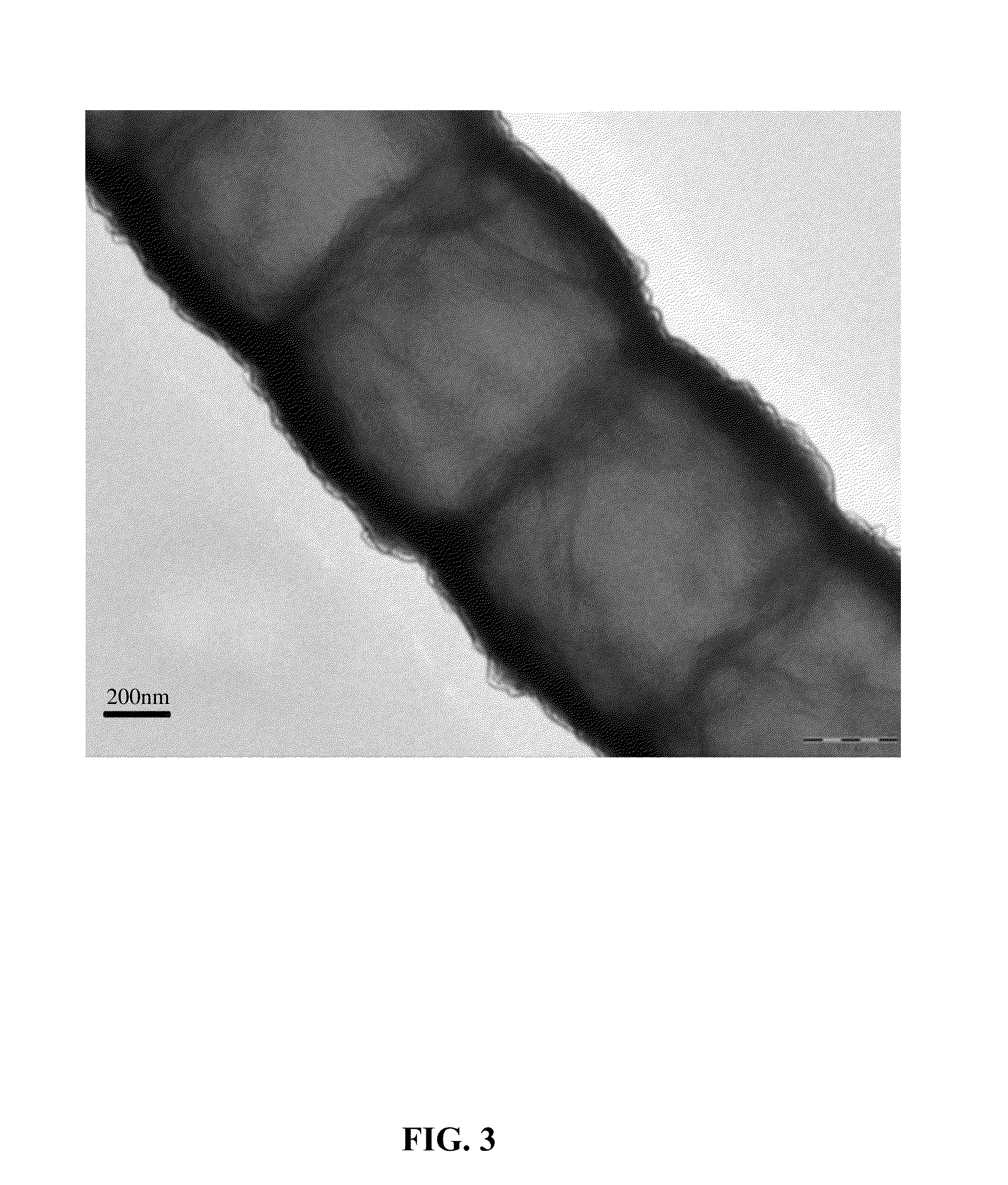
[0066]20 g of a liquid polyacrylonitrile (LPAN) solution (having a molecular weight of 4000) was prepared and stirred for 120 h at a temperature of 120° C. to form a cyclized LPAN solution. The cyclized LPAN solution was then heated for 8 h at a temperature of between 200 and 300° C. to form an OPAN solid comprising a ladder structure. After that, the OPAN solid was ground by a planetary ball grinder. A ratio between a grinding media and the OPAN solid was controlled at 15:1, a grinding speed was controlled at 400 rad / min, and a grinding time was controlled at 8 h. Thereafter, the ground OPAN solid was discharged from the planetary ball grinder, screened, and dried at room temperature to obtain a thermal oxidative precursor.

[0067]The thermal oxidative precursor was then transferred to a combustion boat and was calcined at a temperature of 900° C. for 8 h in the presence of inert gas having a flow rate of 100 mL / min. A resulting product was cooled to room temperature, ground, and scr...

example 2

[0068]20 g of an LPAN solution (having a molecular weight of 4000) was prepared and stirred for 120 h at a temperature of 120° C. to form a cyclized LPAN solution. 0.6 g of SnO2 powder was added to the cyclized LPAN solution as a doping agent (a weight ratio between the doping agent and the LPAN was 0.03:1) to form a mixture. Thereafter, the mixture water ground by a planetary ball grinder. A ratio between a grinding media and the mixture was controlled at 15:1, a grinding speed was controlled at 500 rpm, and a grinding time was controlled at 8 h. A resulting product was discharged out of the planetary ball grinder and then heated at a temperature between 200 and 300° C. for 8 h to form a SnO2-doped OPAN solid comprising a ladder structure. After that, the OPAN solid sample was ground by the planetary ball grinder. The ratio between the grinding media and the OPAN solid sample was controlled at 15:1, the grinding speed was controlled at 400 rad / min, and the grinding time was control...

example 3

[0070]20 g of an LPAN solution (having a molecular weight of 4000) was prepared and stirred for 120 h at a temperature of 120° C. to form a cyclized LPAN solution. 0.6 g of TiO2 powder was added to the cyclized LPAN solution as a doping agent (a weight ratio between the doping agent and the LPAN was 0.03:1) to form a mixture. Thereafter, the mixture water ground by a planetary ball grinder. A ratio between a grinding media and the mixture was controlled at 15:1, a grinding speed was controlled at 500 rpm, and a grinding time was controlled at 8 h. A resulting product was discharged out of the planetary ball grinder and then heated at a temperature between 200 and 300° C. for 8 h to form a TiO2-doped OPAN solid comprising a ladder structure. After that, the OPAN solid sample was ground by the planetary ball grinder. The ratio between the grinding media and the OPAN solid sample was controlled at 15:1, the grinding speed was controlled at 400 rad / min, and the grinding time was control...


PUM

PropertyMeasurementUnit
flow rateaaaaaaaaaa
flow rateaaaaaaaaaa
temperatureaaaaaaaaaa

Abstract

A method for preparing a carbon nanotube, including: a) preparing an LPAN solution, stirring the LPAN solution at between 100 and 200° C. for between 100 and 200 hours to yield a cyclized LPAN solution; b) heating the cyclized LPAN solution at between 200 and 300° C. for between 1 and 10 hours to yield an OPAN; c) grinding, screening, and drying at room temperature the OPAN to yield a thermal oxidative precursor; d) calcining the thermal oxidative precursor at between 400 and 1000° C. for between 1 and 24 h in the presence of inert gas having a flow rate of between 10 and 500 mL / min to yield a carbonated precursor; and e) calcining the carbonated precursor at between 1000 and 1500° C. for between 1 and 10 hours in the presence of the inert gas having a flow rate of between 10 and 500 mL / min to yield a carbon nanotube material.

Description

CROSS-REFERENCE TO RELATED APPLICATIONS[0001]This application is a continuation-in-part of International Patent Application No. PCT / CN2012 / 073615 with an international filing date of Apr. 6, 2012, designating the United States, now pending, and further claims priority benefits to Chinese Patent Application No. 201110086492.7 filed Apr. 7, 2011. The contents of all of the aforementioned applications, including any intervening amendments thereto, are incorporated herein by reference. Inquiries from the public to applicants or assignees concerning this document or the related applications should be directed to: Matthias Scholl P.C., Attn.: Dr. Matthias Scholl Esq., 14781 Memorial Drive, Suite 1319, Houston, Tex. 77079.BACKGROUND OF THE INVENTION[0002]1. Field of the Invention[0003]The invention relates to the field of carbon tube materials, and more particular to a method for preparing a hollow bamboo-shaped carbon nanaotube or microtube.[0004]2. Description of the Related Art[0005]As ...

Claims


Application Information

Patent Timeline
Patent Type & Authority Applications(United States)
IPC IPC(8): C01B31/02H01B1/04
CPCH01B1/04C01B31/0226B82Y30/00B82Y40/00C01B32/16C01B32/18C01B32/05D01F9/22
Inventor LIU, JIANHONGXU, JIANWU, SHUANGQUAN
Owner LIU JIANHONG
Why Eureka
Try Eureka