Vehicle temperature control apparatus and in-vehicle thermal system

a temperature control apparatus and in-vehicle technology, which is applied in the direction of lighting and heating apparatus, battery/fuel cell control arrangement, instruments, etc., can solve the problems of increasing the weight of the vehicle, reducing the cruising range of the electric vehicle, and a large installation space in the vehicle, so as to reduce the energy used to drive the compressor which constitutes the air-conditioning device, the degree of supercooling of the refrigerant coming out of the condenser is increased

Inactive Publication Date: 2014-02-13
DENSO CORP
View PDF7 Cites 128 Cited by
  • Summary
  • Abstract
  • Description
  • Claims
  • Application Information

AI Technical Summary

Benefits of technology

[0022]In this case, when the secondary battery is charged, the cooler cools the cooling fluid and the closed circuit is formed for the circulation of the cooling fluid through the battery heat exchanger, the bypass passage and the pump. Therefore, the cold energy is stored in the cooling fluid and in the secondary battery. Then, after completion of charging of the secondary battery, a closed circuit is formed to circulate the cooling fluid through the battery heat exchanger, the refrigerant-cooling heat exchanger, and the pump. Therefore, the refrigerant is cooled by the refrigerant-cooling heat exchanger with the cold energy stored in the cooling fluid and in the battery. Thus, the degree of supercooling of the refrigerant which comes out from the condenser is increased, and the efficiency of the air-conditioning device is improved. Thus, the energy for driving the compressor which constitutes the air-conditioning device is reduced. As a result, a power required for the inside air-conditioning of the vehicle compartment is reduced by using the cold energy stored in the secondary battery.

Problems solved by technology

Thus, in summer and in winter during which a large amount of energy is required for the air conditioning, a cruising range of the electric vehicle may decrease.
However, in such technique, a large amount of a heat storage material or a cold storage material is required, thereby causing an increased vehicle weight or a large installation space in the vehicle.
However, such heating capacity may be difficult to be obtained because it does not necessarily provide sufficient energy for heating the vehicle compartment especially in winter during which temperature difference between the battery temperature and the temperature of the inside air in the vehicle compartment is not large enough for providing a required amount of heat.
That is, the heat capacity of a large capacity battery is not fully utilized in the patent document 2.
According to the conventional art of the patent documents 3 and 4, in addition to the same problem as the conventional art of the above-mentioned patent document 2, a temperature difference between the battery temperature and an inside air temperature of the vehicle compartment is also not sufficient in a cooling operation, which leads to an insufficient cooling capacity of the cooling operation.
Further, even when the in-house air is introduced to the vehicle, the same problem of insufficient temperature difference is caused, and thereby it may difficult to obtain a sufficient heating / cooling capacity.
Further, for the air introduction directly into the vehicle from the house, a hose is required, thereby complicating the structure of such system.

Method used


Image

  • Vehicle temperature control apparatus and in-vehicle thermal system
  • Vehicle temperature control apparatus and in-vehicle thermal system
  • Vehicle temperature control apparatus and in-vehicle thermal system

Examples


first embodiment

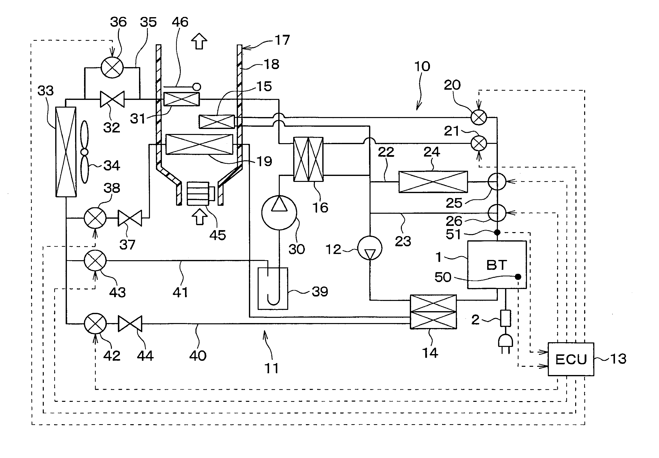
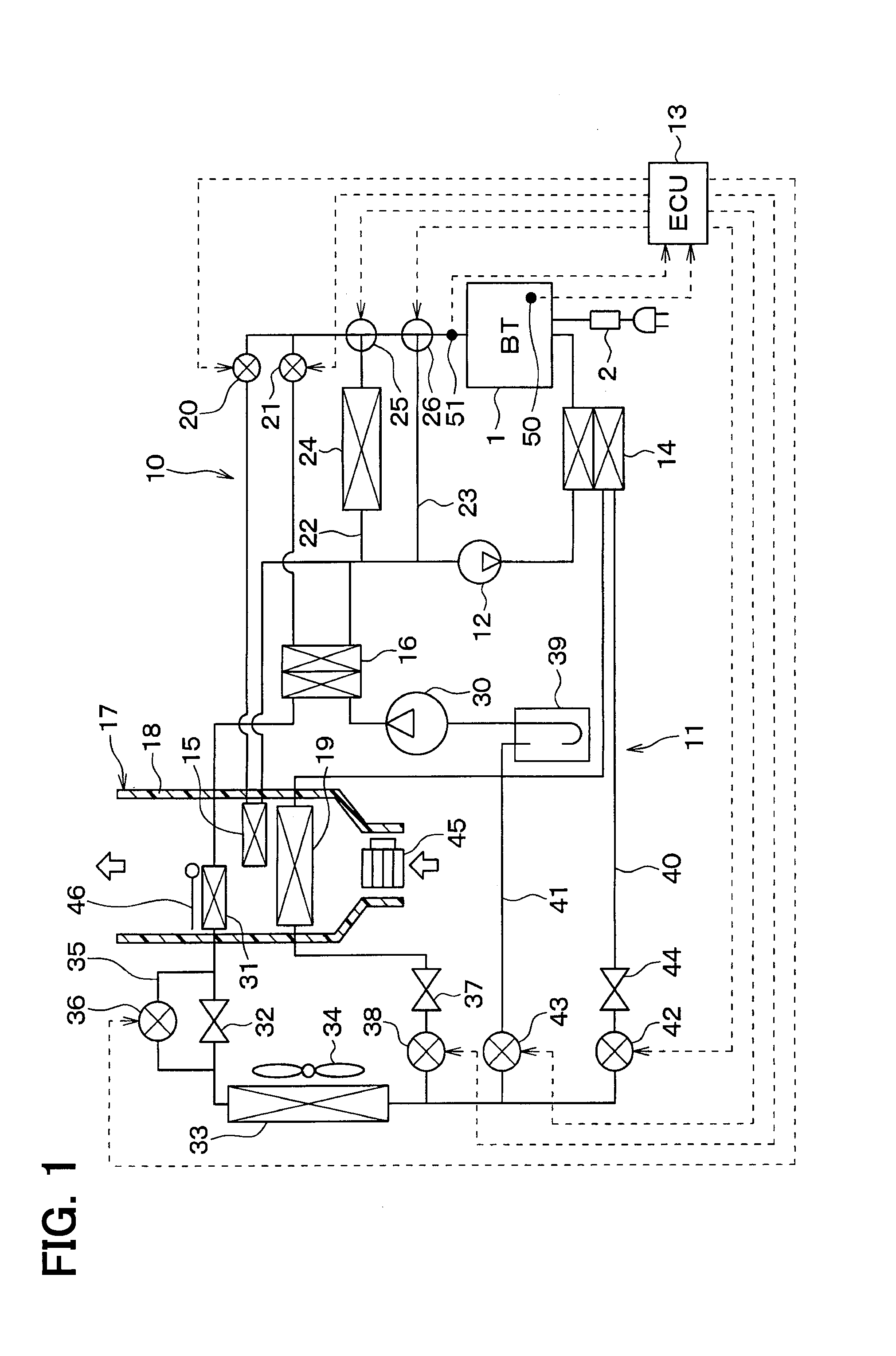
[0052]The first embodiment is described in the following. FIG. 1 is an overall schematic diagram of a temperature control apparatus for vehicles in the present embodiment. The temperature control apparatus for vehicles in the present embodiment is used as a vehicular air-conditioner, and uses air in a vehicle compartment as a temperature control object.

[0053]Specifically, the temperature control apparatus for vehicles in the present embodiment is used as a vehicular air-conditioner of a plug-in hybrid vehicle (i.e., an electric vehicle). The plug-in hybrid vehicle is a vehicle which can charge an electric power supplied from an external power supply (i.e., a commercial power supply) at a time of stop of the vehicle to a secondary battery (i.e., a high-voltage battery), from among hybrid vehicles that derive a drive power for a travel of the vehicle from both of an internal combustion engine and an electric motor for a travel of the vehicle.

[0054]In addition, the temperature control ...

second embodiment

[0157]Although the above-described first embodiment is presented as an example configuration in which the refrigeration cycle 11 serves as a heat pump cycle that is usable for both of the heating operation and the cooling operation, a refrigeration cycle 11 in this second embodiment of the present disclosure is used as a cooler cycle for the cooling operation of the vehicle compartment, as shown in FIGS. 10 (a), (b), (c).

[0158]More specifically, in the second embodiment, the interior condenser 31, the air amount adjustment door 46, the first expansion valve 32, the expansion valve bypass passage 35, the first electromagnetic refrigerant valve 36, the second bypass refrigerant passage 41, and the fourth electromagnetic refrigerant valve 43 described in the above-described first embodiment are now omitted.

[0159]In an example of FIG. 10 (a), the second coolant-refrigerant heat exchanger 16 is disposed in the refrigeration cycle 11 between the exterior heat exchanger 33 and the second a...

third embodiment

[0161]The third embodiment further adds an inner heat exchanger 47 to the examples of the above-described second embodiment, as shown in FIGS. 11 (a), (b), (c).

[0162]The inner heat exchanger 47 is used for heat exchange between the high-pressure refrigerant flowing out of the exterior heat exchanger 33 and the low-pressure refrigerant flowing out of one of the first coolant-refrigerant heat exchanger 14 and the interior evaporator 19. Thus, the inner heat exchanger 47 cools the high-pressure refrigerant flowing out of the exterior heat exchanger 33, for realizing an enthalpy reduction function for reducing an enthalpy of the refrigerant that flows into the interior evaporator 19 and for realizing a liquid compression suppression function for preventing a liquid compression in the compressor 30 by raising an enthalpy of the sucked refrigerant to be sucked into the compressor 30 to a level that makes the sucked refrigerant of the compressor 30 to be in a gas phase.

[0163]In an example ...


PUM


Abstract

A vehicle temperature control apparatus for controlling temperature of a temperature control object, which is at least one of inside air of a vehicle compartment and a vehicle component, includes a heat capacitive element capable of storing heat, a refrigeration cycle in which heat is absorbed from a low temperature side and is dissipated to a high temperature side, a heat exchanger that causes the heat capacitive element to exchange heat with refrigerant of the refrigeration cycle, and a heat dissipation portion which dissipates heat in the refrigerant of the refrigeration cycle to the temperature control object. Thus, a temperature control by using the heat capacitive element can be effectively performed.

Description

CROSS REFERENCE TO RELATED APPLICATION[0001]The application is based on Japanese Patent Applications No. 2011-091847 filed on Apr. 18, 2011 and No. 2012-038731 filed on Feb. 24, 2012, the contents of which are incorporated herein by reference in their entirety.FIELD OF THE INVENTION[0002]The present invention relates to a vehicle temperature control apparatus which performs a temperature control of at least one of air in a vehicle compartment and a component in a vehicle, and an in-vehicle thermal system.BACKGROUND OF THE INVENTION[0003]Conventionally, in electrically-driven vehicles such as an electric vehicle, a hybrid vehicle and the like, a motor is used to drive those vehicles by using an electric energy supplied from a battery or the like. The electric energy required for air-conditioning in the vehicle is also supplied from the battery. Thus, in summer and in winter during which a large amount of energy is required for the air conditioning, a cruising range of the electric ve...

Claims


Application Information

Patent Timeline
Patent Type & Authority Applications(United States)
IPC IPC(8): B60H1/00
CPCB60H1/00735B60H1/00899B60H2001/00928B60H2001/00949B60L1/003B60L1/02B60L1/08B60L2240/34B60L2240/36B60L2240/545B60L2240/662B60L2250/12B60L2270/44B60L2270/46B60L53/14B60L58/26B60L58/27B60H1/00499Y02T10/70Y02T10/7072Y02T10/72Y02T90/14Y02T90/16
Inventor TAKEUCHI, MASAYUKIKISHITA, HIROSHIOMI, YASUMITSUKAKEHASHI, NOBUHARUOKAWA, HIDEAKIMIURA, KOUJINISHIKAWA, MICHIO
Owner DENSO CORP
Why Eureka
Try Eureka