
Defect Inspection Apparatus And Defect Inspection Method

a technology of defect inspection and inspection apparatus, which is applied in the direction of optical radiation measurement, photometry using electric radiation detectors, instruments, etc., can solve the problems of high resistance to input power, high wavelength conversion efficiency of wavelength conversion optical system, and difficulty in achieving necessary processing accuracy, so as to reduce wavelength, enhance output power, and improve the effect of defect detection sensitivity

Active Publication Date: 2014-02-13
HITACHI HIGH-TECH CORP
View PDF11 Cites 3 Cited by
  • Summary
  • Abstract
  • Description
  • Claims
  • Application Information

AI Technical Summary

Benefits of technology

The patent text describes a method to improve defect detection in a manufacturing process using a pulse oscillation type of laser and large NA detection optics. The laser is able to generate high output power in a short-wavelength region, and the spectral bandwidth is narrowed down to reduce chromatic aberration. This allows for better detection of defects, even at very low light levels. The use of highly workable glass materials and non-symmetrical lens shapes helps to meet the necessary surface accuracy and profile irregularity conditions. Overall, this patent aims to enhance defect detection sensitivity and improve the efficiency of defect detection systems.

Problems solved by technology

To realize a light source of high output at a short wavelength, it becomes an issue how to construct a wavelength conversion optical system having high wavelength-conversion efficiency and high resistance to input power.
Increasing the number of lenses, however, tightens requirements relating to permissible surface accuracy or profile irregularity per lens and makes it difficult to achieve necessary processing accuracy.
In DUV regions, it is also difficult to reduce chromatic aberration since the types of glass materials that can be used are limited because of the significant dispersion of the glass cubes.
Additionally, mounting a plurality of detection optics requires using an oval lens aperture, and it is difficult to realize the lenses whose surface accuracy or profile irregularity requirements can be met even if the lens does not have a rotationally symmetrical shape.

Method used


Image

  • Defect Inspection Apparatus And Defect Inspection Method
  • Defect Inspection Apparatus And Defect Inspection Method
  • Defect Inspection Apparatus And Defect Inspection Method

Examples


first embodiment

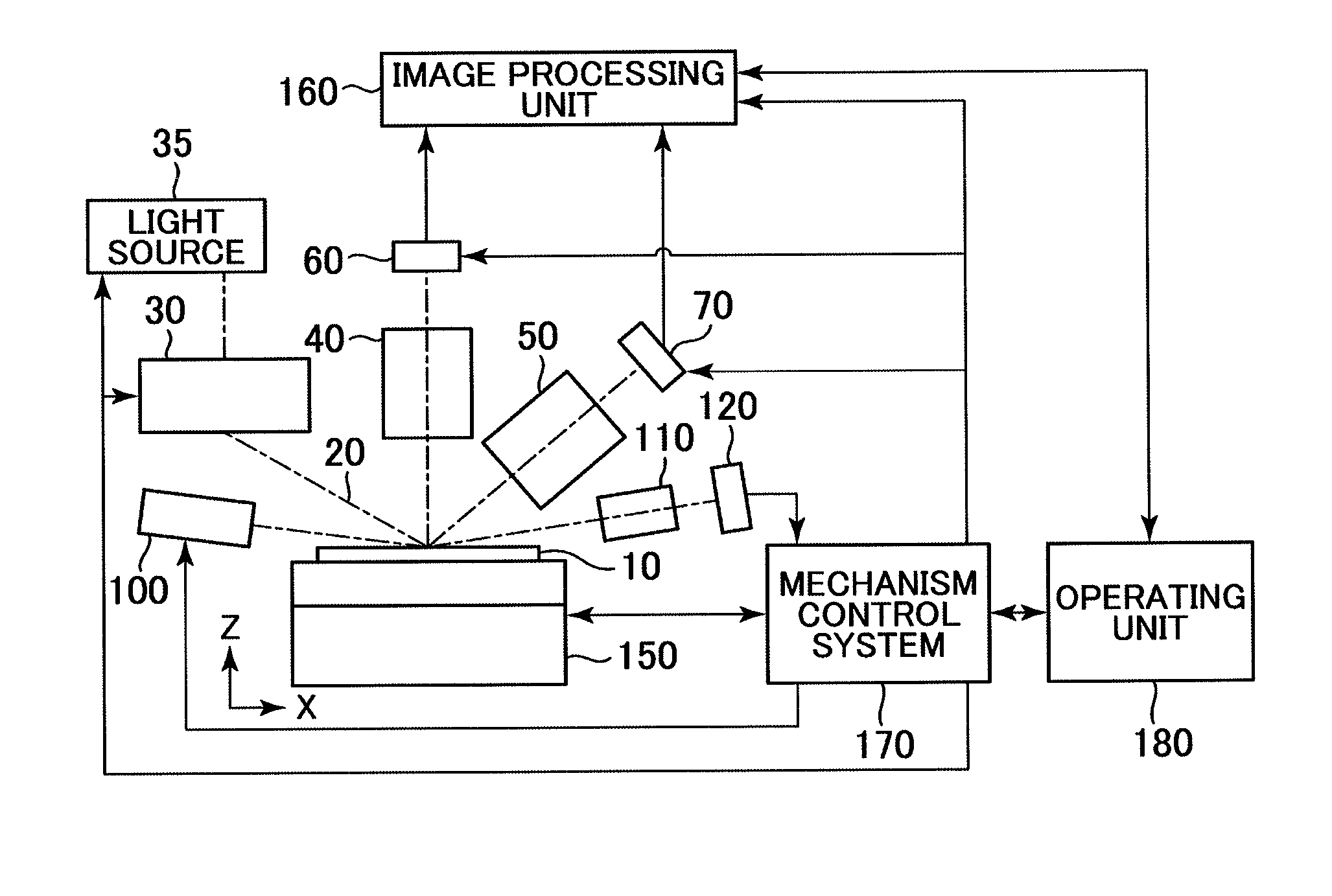
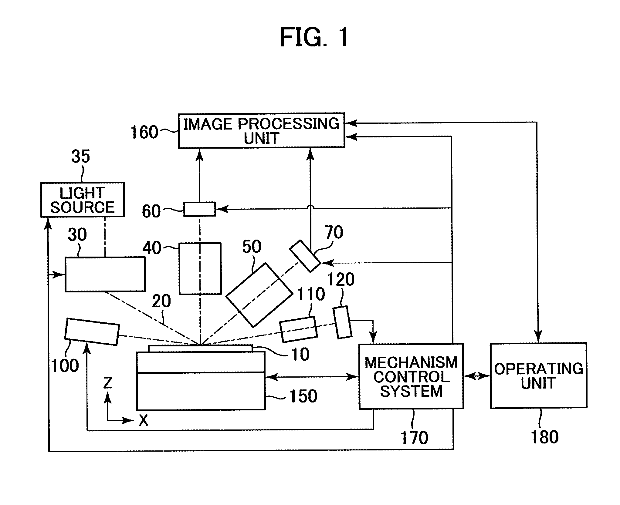
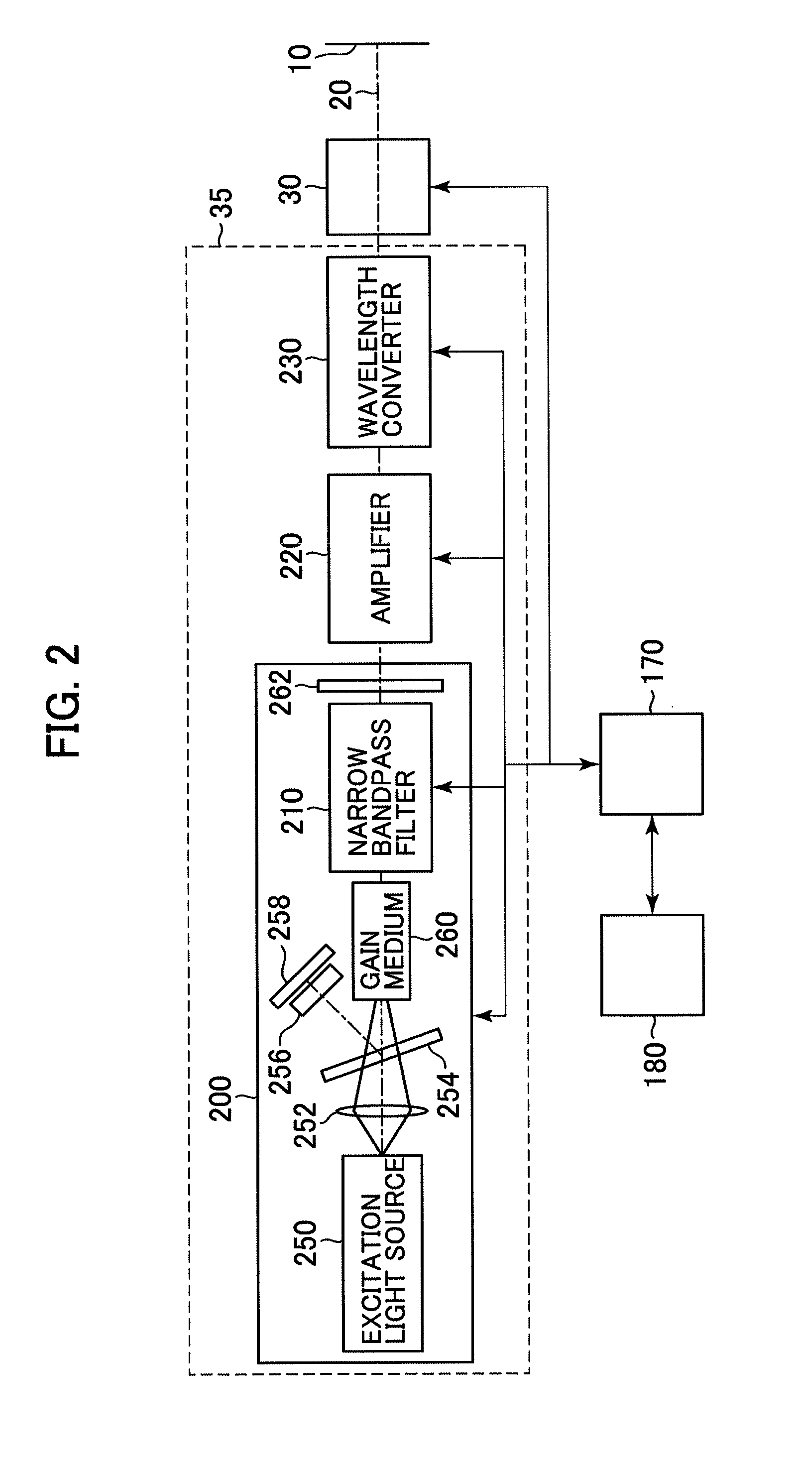
[0024]FIG. 1 shows an overall configuration of a defect inspection apparatus according to the present embodiment. A sample 10 (such as semiconductor wafer, display element, printed circuit substrate, or the like) that is to be inspected is mounted on a stage 150. The stage 150 is constructed as a combination of, for example, an X-Y stage, a Z-stage, a θ-stage, and other elements. The stage 150 is arranged so that the sample can be scanned in an X-Y plane to allow for inspection of the entire sample surface through detection optics 40 and 50 placed above. The sample 10 has its thin linear surface region illuminated with illumination light 20 that has exited a light source 35 and passed through an illumination optical system 30. Of the light backscattered from patterns, contamination, and / or the like present on the sample, only light incident upon the detection optics 40, 50 placed above the sample is guided to sensors 60 and 70, then undergoes photoelectric conversion, and is sent as...


PUM

PropertyMeasurementUnit
infrared-light wavelength regionsaaaaaaaaaa

Abstract

Method for realizing an inspection with short wavelength, high power light source and large numerical aperture, high performance optics to improve defect inspection sensitivity is disclosed. Short wavelength high power laser is realized by using a pulse oscillation type laser suitable for generation of high output power in a short-wavelength region, In addition, a spectral bandwidth of the laser is narrowed down so that amount of chromatic aberration of detection optics with single glass material (i.e. without compensation of chromatic aberration) is lowered to permissible level. Using highly workable glass material to construct the detection optics enables necessary surface accuracy or profile irregularity conditions to be met, even if the number of lenses is increased for large NA or the lens doesn't have a rotationally symmetrical aperture.

Description

BACKGROUND OF THE INVENTION[0001]1. Field of the Invention[0002]The present invention relates to a defect inspection apparatus and a method for inspecting an occurrence status of dust, dirt, other foreign matter, and surface defects such as pattern defects, when patterns are formed on the substrate and necessary components are fabricated thereon. Such fabrication processes include manufacturing processes for semiconductors, flat-panel displays such as liquid-crystal display elements, printed circuit substrates, or the like.[0003]2. Description of the Related Art[0004]In semiconductor-manufacturing processes, defects in pattern shape occur due to the presence of dust, dirt, and other foreign substances (hereinafter, referred to collectively as contamination) on the surface of a semiconductor substrate (wafer), and / or due to improper formation of electrical interconnection patterns. Such defects will cause improper electrical insulation of interconnections, short-circuiting, increased...

Claims


Application Information

Patent Timeline
Patent Type & Authority Applications(United States)
IPC IPC(8): G01N21/95
CPCG01N21/95G01N21/95684G01N21/956G01N21/94G01N21/33G01N21/47G01N2201/06113G01N2201/0697G01N21/9501
Inventor SHIMURA, KEI
Owner HITACHI HIGH-TECH CORP
Learn More