Apparatus for producing carbon nanomaterial, and use thereof

Active Publication Date: 2014-03-13
ENVIRONMENT ENERGY NANOTECH RES INST COLTD
View PDF3 Cites 8 Cited by
  • Summary
  • Abstract
  • Description
  • Claims
  • Application Information

AI Technical Summary

Benefits of technology

[0011]The present application has been created to resolve the above-described problems, and it is an objective thereof to provide a method for producing a single-walled or multi-walled carbon nanomaterial at low cost and with good efficiency.
[0012]In view of the abovementioned problems, the inventors have investigated what causes the low yield of carbon nanomaterials in the arc discharge method. The results obtained suggest that simultaneously with the formation of single-walled and multi-walled carbon nanomaterials by rapid cooling of carbon vapor produced by arc discharge,

Problems solved by technology

The problem associated with the abovementioned methods is that the yield of the carbon nanomaterial related to the consumed amount of carbon starting material is very small.
Further, where a carbon nanomaterial is produced in vacuum or liquid nitrogen, the investment in equipment for maintaining vacuum or low temperature is high and the cost of maintenance and control is also high.
In

Method used


Image

  • Apparatus for producing carbon nanomaterial, and use thereof
  • Apparatus for producing carbon nanomaterial, and use thereof
  • Apparatus for producing carbon nanomaterial, and use thereof

Examples


example 1

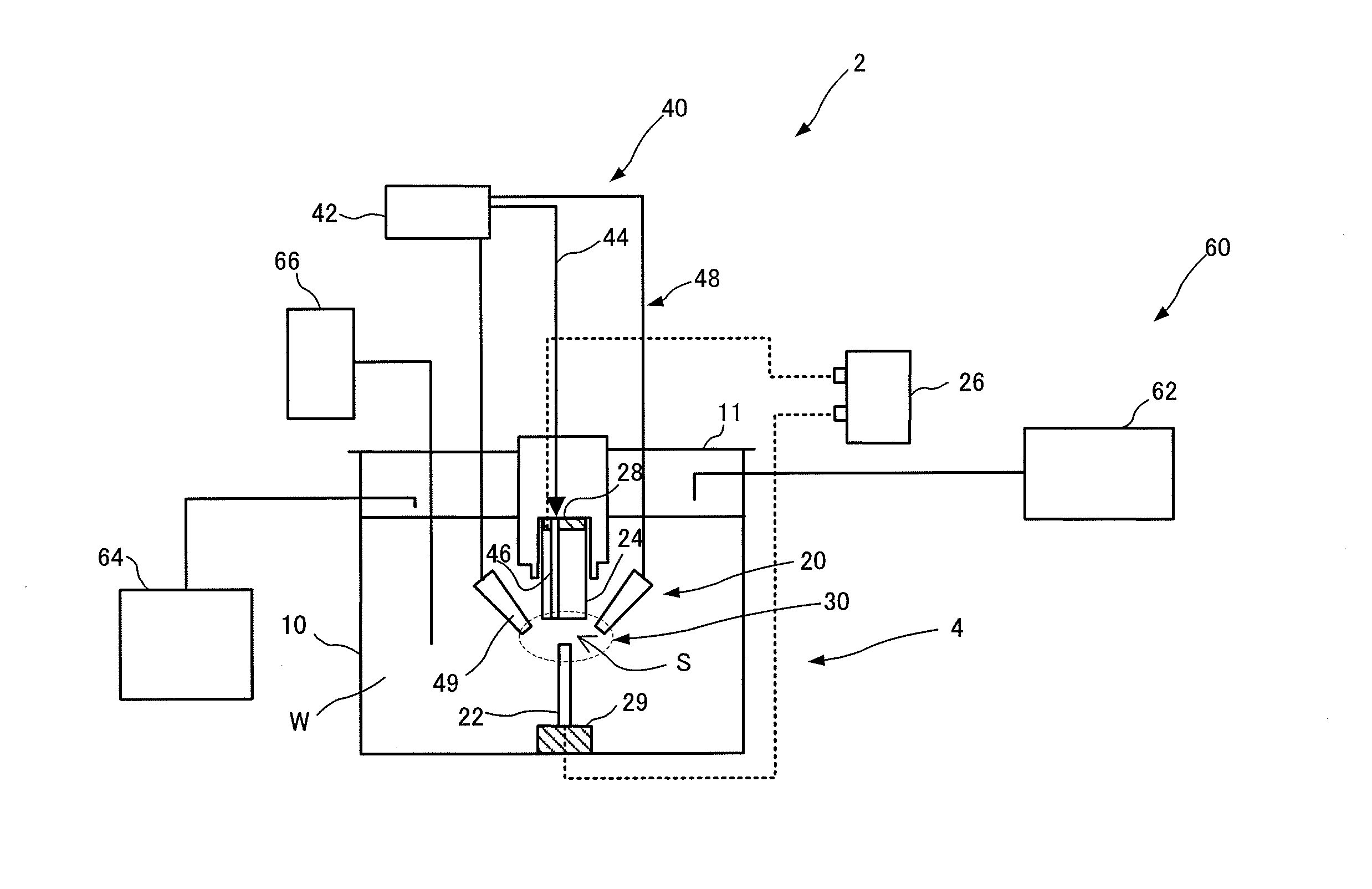
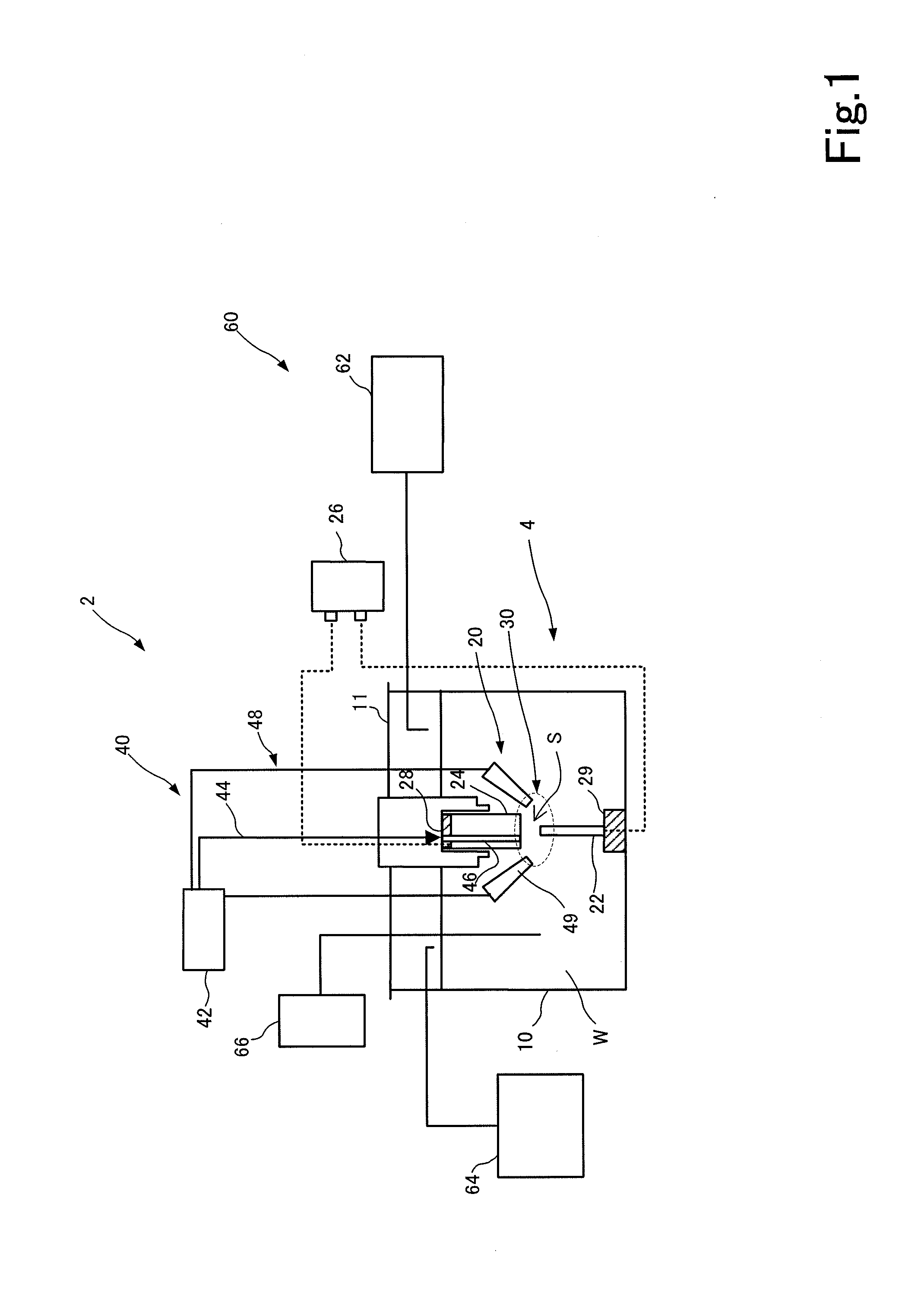
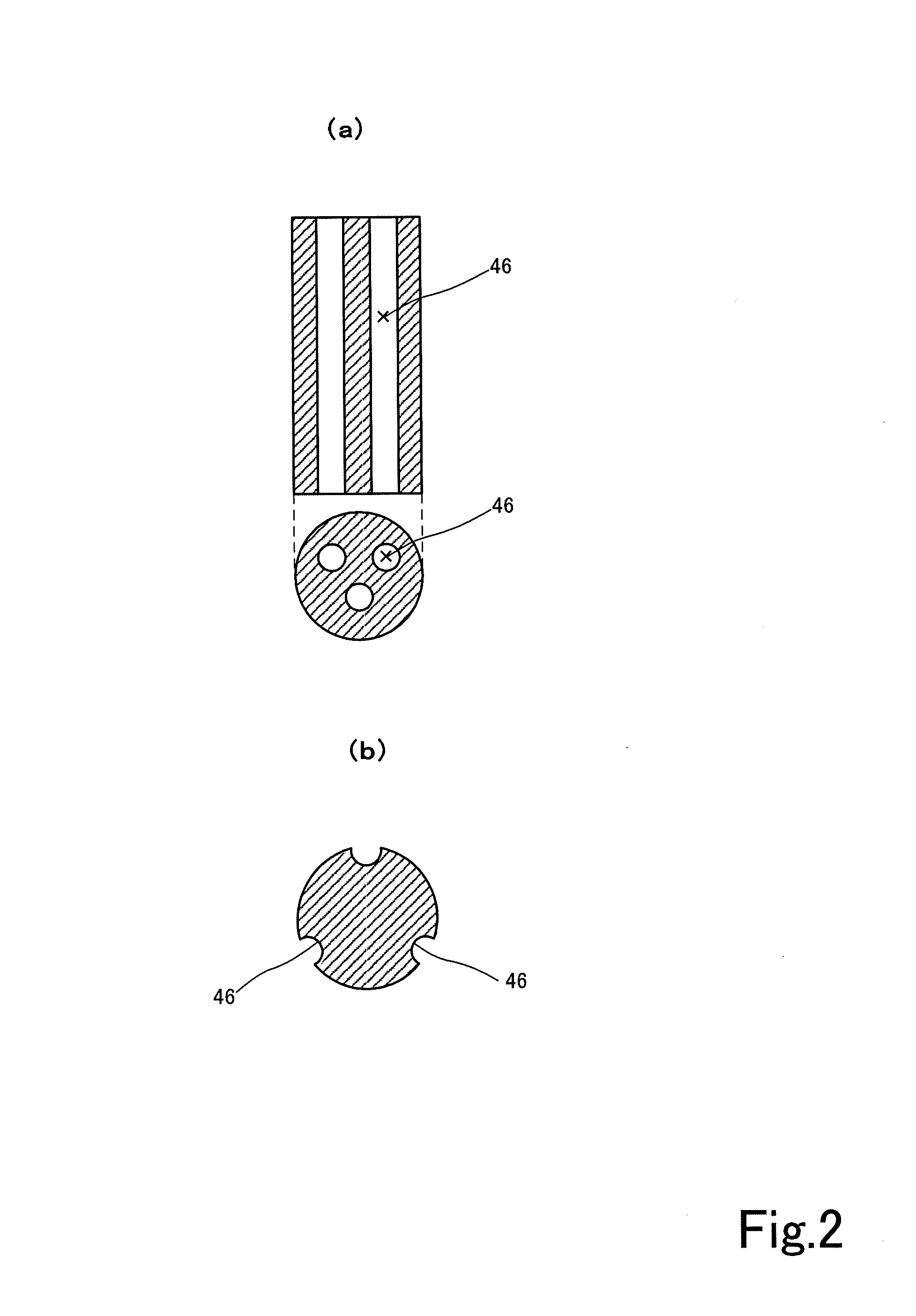
[0102]The present example is explained as a preferred example of the apparatus 2 for producing a carbon nanomaterial which is shown in FIG. 1. The graphite positive electrode 22 and the negative electrode 24 are disposed in the aqueous medium tank 10 with a water depth of about 30 cm so that the electrodes face each other in the vertical direction in relation to force of gravity at a distance of 1 mm from each other. The graphite positive electrode has a cylindrical shape with a diameter of 6 mm and a length of 100 mm and is obtained using 7 g of carbon rods with a carbon purity of 99.999%. The aqueous medium tank is filled with 30 L of aqueous solution, and the aqueous medium tank is then sealed with a lid. A DC voltage of 20 V, 140 A is applied to the graphite positive electrode and the negative electrode. Carbon nanohorns are then synthesized by supplying nitrogen gas at 5 L / min at the initial stage of arc discharge (3 sec to 5 sec) to the introducing path 46 of the inert gas sup...

example 2

[0107]In the present example, the electric conductivity of the carbon nanohorns obtained in Example 1 is estimated. A plurality of types of buckypaper is fabricated by the following method by using commercially available carbon nanotubes (purity 99%, Baytubes (trade name), manufactured by Bayer) and the carbon nanohorns obtained in Example 1.

[0108]Thus, buckypaper 1 (thickness 37 μm) is fabricated by preparing a carbon nanotube dispersion in which carbon nanotubes are dispersed in deionized water or pure water by ultrasonic treatment by using appropriate gum arabic, subjecting the dispersion to solid-liquid separation, as appropriate, by centrifugal separation to adjust the concentration (0.2 wt %), then filtering under 6 atm, and drying the carbon nanotubes separated on a polycarbonate filter (pore diameter 0.45 μm) under reduced pressure at room temperature (about 20° C. to 23° C.).

[0109]Buckypaper 2 is fabricated by using a carbon nanohorn dispersion of Example 1 that has been ac...

example 3

[0117]In the present example, friction properties of the carbon nanohoms obtained in Example 1 are evaluated. Thus, a friction coefficient μ in a low-load range is measured between two steel plates. The following device and method are used for the measurements.

[0118]1. Device

[0119]Steel gauge block: length 4 mm (weight 8 g), 5 mm (weight 10 g), 10 mm (weight 21 g), 20 mm (weight 49 g), and 30 mm (weight 73 g); stainless steel×90CrMoV18; surface hardness 56HRC; Rz=0.1 μm.

[0120]Steel base: stainless steel×90CrMoV18; surface hardness 56HRC; Rz=0.1 μm.

[0121]Spring meter: 1 g to 8 g / l N to 40 N (Correx).

[0122]Force sensor: Transcal 7280 (up to 20 N) (Burster).

[0123]Digital meter: digital meter manufactured by Maul.

[0124]PELT meter: roughness and topography measurements (Mahr).

[0125]2. Method

[0126]The weight of the gauge block is measured with the digital meter. Then the surface roughness of the gauge block and the steel base is measured with the PELT meter, and then the friction force at...


PUM

PropertyMeasurementUnit
Lengthaaaaaaaaaa
Lengthaaaaaaaaaa
Electrical conductivityaaaaaaaaaa

Abstract

The present disclosure provides a method for producing carbon nanoparticles at low cost and with good efficiency. According to the disclosure of the present description, a voltage is applied between a graphite positive electrode and a negative electrode in an aqueous medium to generate arc discharge in a gap. An inert gas is introduced into the gap from a cylinder bottle at a predetermined flow rate. In this manner, carbon nanoparticles can be produced from carbon steam that is generated in the gap as a result of the arc discharge.

Description

TECHNICAL FIELD[0001]The present application relates to an apparatus for producing a carbon nanomaterial by arc discharge and use thereof.BACKGROUND ART[0002]Carbon substances having nanometer-scale microstructures, such as single-walled or multi-walled carbon nanotubes, carbon nanohorns, fullerenes, and nanocapsules, have recently attracted much attention. Such carbon substances are expected to find applications as nanostructured graphite substances for new electronic materials, catalysts, and optical materials. In particular, carbon nanohorns have attracted attention as substances that are the closest to practical use in electrode materials or gas-adsorbing materials of fuel cells.[0003]An arc discharge method, a chemical vapor deposition (CVD) method, and a laser ablation method have been used for producing such carbon nanomaterials. In particular, a variety of methods for producing carbon nanoparticles by arc discharge has been disclosed because nanotubes produced by the arc dis...

Claims


Application Information

Patent Timeline
IPC IPC(8): C01B31/02
CPCC01B31/0293B82Y30/00B82Y40/00C01P2002/82C01P2002/88C01P2004/16C01P2004/64B01J20/28028B01J20/3078B01J20/3208B01J20/3234B01J20/3293B01J20/3295B01J20/28045B01J20/205C01B32/15C01B32/18C01B32/16B01J20/20B01J20/30
Inventor GOINO, TADASHI
Owner ENVIRONMENT ENERGY NANOTECH RES INST COLTD
Why Eureka
Try Eureka