Control Module for Deposition of Optical Thin Films

a control module and thin film technology, applied in the direction of programme control, total factory control, electric programme control, etc., can solve the problems of false interpretation of signal changes, components not necessarily designed to integrate with each other, and the most difficult deposition step

Inactive Publication Date: 2014-05-15
GALEB RANKO
View PDF5 Cites 14 Cited by
  • Summary
  • Abstract
  • Description
  • Claims
  • Application Information

AI Technical Summary

Benefits of technology

[0041]Another object of this invention is to incorporate a Programmable Logic Controller (PLC) in the deposition controller. The PLC replaces a number of standalone electronic components and eliminates multiple communication links between the devices. The PLC increases the input / output capability of the system and provides more reliable and easier implementation of the communication between the host application and the deposition controller. The PLC hardware is off-the-shelf product readily available from several manufacturers of the electronic components. The PLC can be easily configured to connect to the TCP / IP networks. The PLC provides a digital computer with multiple input and output arrangements ideally suited for the integration of the individual components from the paragraph [0015] into a single control module, with the exception of the optical monitor component where only certain functions of the optical monitor can be integrated within the PLC. The PLC program that controls the logic and the functionality of the integrated components is typically written in a special application on a personal computer, and downloaded to the PLC using the Ethernet connection. The program is stored in the PLC in battery-backed-up RAM (random access memory).
[0043]A further object of the invention is to provide a deposition controller that is programmed to examine a run sheet file for its integrity with respect to the minimum layer optical thickness (MLOT) requirement expressed in terms of the quarter wave optical thickness (QWOT). When the deposition controller opens a given run sheet, a software application on the local computer can check the run sheet for compliance. The software application should check the run sheet file before the run sheet is executed in order to avoid starting a non-compliant run. By insuring the run sheet is compliant using the MLOT, a polynomial curve fitting algorithm can be utilized without error during the optical monitoring of the film thickness.
[0044]A further object of the invention is to provide a deposition controller that is programmed to fit a function to a set of discrete data points taken over time during the deposition process. The data points are the values of the signal generated by the optical monitor that represents intensity of the light reflected or transmitted by the growing thin film. The optical monitor can be set to the monitoring wavelength of interest. The number of data points should be as high as possible, but not so numerous to prevent efficient fitting of the function. An example of a method for fitting a curve to a set of data points is an optimized polynomial regression technique. The deposition controller can be programmed to calculate the first and second derivatives of the function. In turn, the deposition controller can accurately predict the occurrence of the turning point, and calculate the number of the turning points. Making decisions regarding the termination of the layer deposition which are based on the optimized polynomial regression technique greatly reduces false termination points due to the low signal-to-noise ratio, or the presence of the ambient noise in the optical monitor signal.

Problems solved by technology

The deposition step has been the most challenging part of the process control because the deposition step is based on the master-slave relationship between different electronic components.
The components are not necessarily designed to integrate with each other.
In the prior art, the optical monitor signals are not analyzed by the optical monitors or the control software utilizing an optimized polynomial regression function technique described below, but rather by a technique that is less accurate, and also prone to false interpretation of the signal change when the signal-to-noise ratio is low, or when the ambient noise interferes with a signal.
Regardless of which method of layer sequencing is established, majority of the commercially available vacuum deposition systems suffer from the same drawback of an incomplete transfer of the relevant data for a particular coating design that has to be implemented in the production machine.
For complex processes, in particular those based on co-deposition of two or more coating materials, synchronizing communication between individual hardware components, while simultaneously performing demanding mathematical calculations related to the optical monitoring, becomes impossible for traditional controllers.
Manual entry of data leads to mistakes.
Typically, the mistakes take the form of data that the deposition controller or the operating software of the coating machine cannot detect, or detects when the process has already started and advanced into the layer execution.
However, without an extensive mathematical knowledge of the history of the signal, the accuracy of detecting a turning point or counting the number of turning points can be greatly compromised due to the presence of the ambient noise or low signal-to-noise ratio.

Method used


Image

  • Control Module for Deposition of Optical Thin Films
  • Control Module for Deposition of Optical Thin Films
  • Control Module for Deposition of Optical Thin Films

Examples


Embodiment Construction

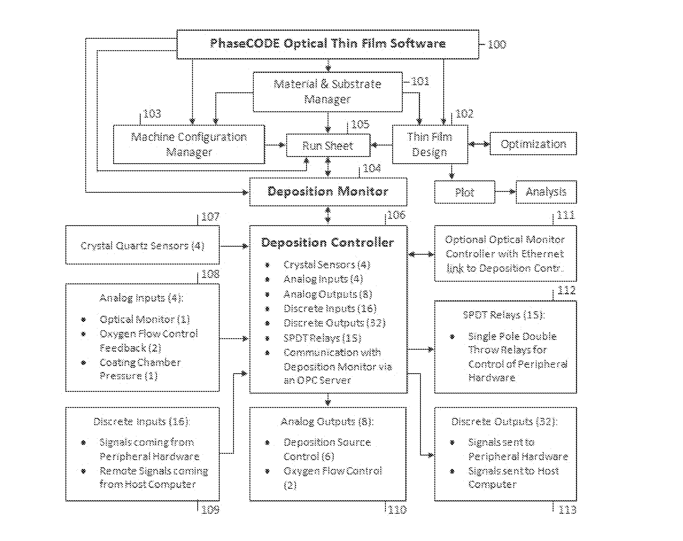
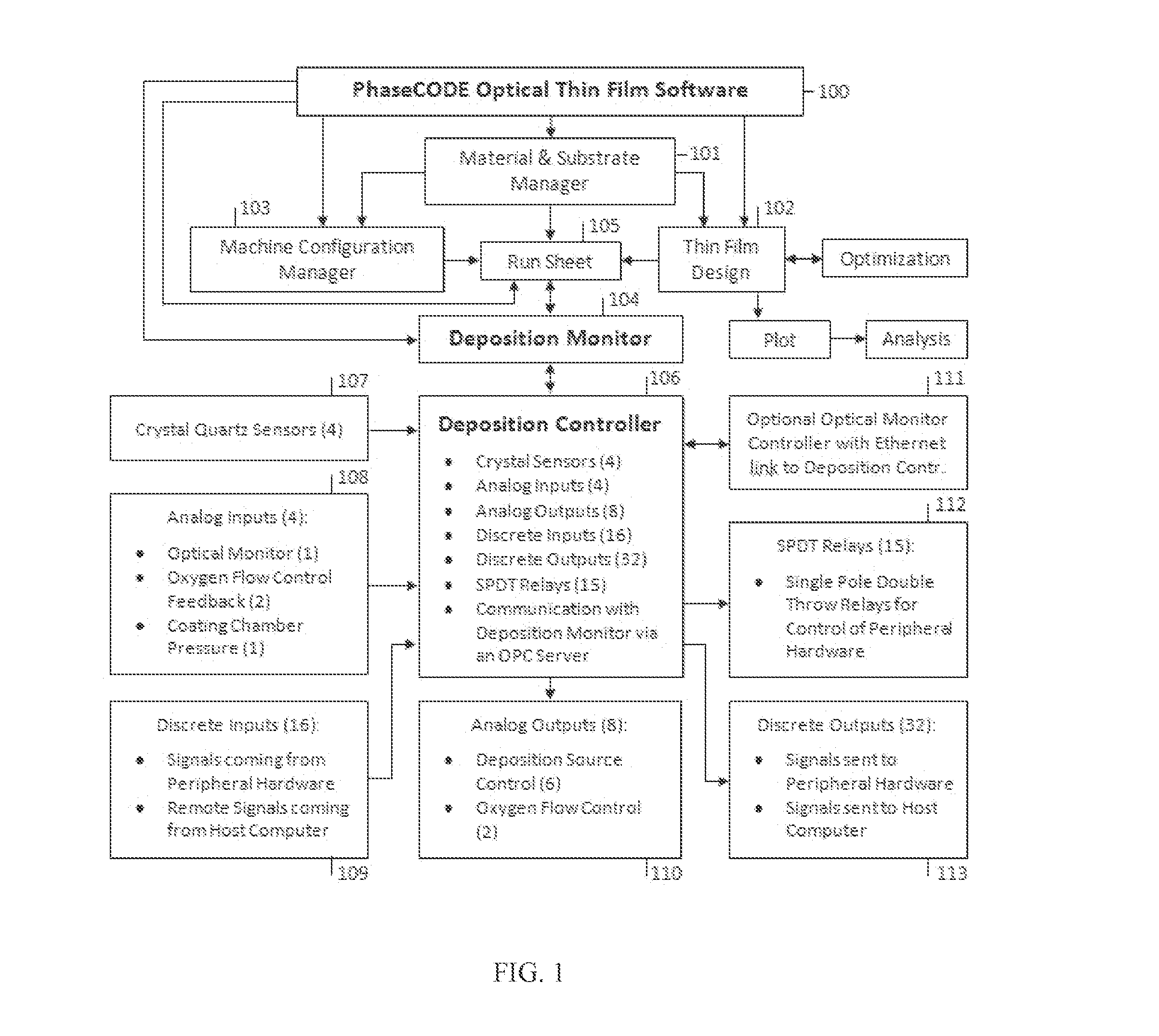
[0064]FIG. 1 is the flowchart representing a functional relationship between the different modules of the optical thin film software 100, such as the PhaseCODE available from Galeb Optics of Trinity, Fla., and a deposition controller 106. The software 100 runs on a local computer, which is not shown. The local computer includes a network interface controller (NIC). In a preferred embodiment, the NIC communicates using the TCP / IP protocol. At box 101, the coating materials and substrates are defined in terms of the refractive indices and the extinction coefficients for the range of wavelengths. Three preferred regression methods can be used for interpolation and extrapolation of material and substrate data: polynomial, rational function, and linear. Corresponding data is available to other program modules through the application database. At box 102, a coating design is created or modified using materials and substrates defined in box 101. At box 103, a coating machine configuration ...


PUM


Abstract

The deposition controller controls a coating machine used in the deposition of the thin film coatings. The deposition controller is particularly useful for the deposition of multiple layers or co-deposition of multiple materials. The integrated system is a single hardware unit controlled by the software residing on the local computer. The single unit combines the functionality of a deposition controller, mass flow controller, quartz crystal controller, optical monitor chip change controller, and an optical monitor signal analyzer. The integrated system utilizes a Programmable Logic Controller (PLC) for the purpose of controlling the deposition process. A run sheet file is used by the system to create a set of process parameters. The system also examines a run sheet file at the time of its opening for its integrity with respect to the minimum layer optical thickness requirement expressed in terms of QWOT (quarter wave optical thickness). The controller utilizes an optimized polynomial regression function technique for the accurate layer termination while monitoring the reflection or transmission function and calculating its first and second derivatives to eliminate false termination points.

Description

CROSS-REFERENCE TO RELATED APPLICATIONS[0001]This application claims the benefit of U.S. Provisional Application No. 61 / 725,289, filed Nov. 12, 2012.STATEMENT REGARDING FEDERALLY SPONSORED RESEARCH OR DEVELOPMENT[0002]Not ApplicableTHE NAMES OF PARTIES TO A JOINT RESEARCH AGREEMENT[0003]Not ApplicableINCORPORATION-BY-REFERENCE OF MATERIAL SUBMITTED ON A COMPACT DISC[0004]Not ApplicableBACKGROUND OF THE INVENTION[0005]1. Field of the Invention[0006]The invention relates to devices for controlling and monitoring vacuum deposition of thin films, especially thin films for optical applications.[0007]2. Description of the Related Art[0008]U.S. Pat. No. 4,311,725 issued in January, 1982, to Leslie Holland for a, “Control of Deposition of Thin Films”.[0009]The multifaceted nature of optical thin films, expressed in terms of the refractive index, extinction coefficient, physical thickness, optical thickness, and the phase thickness can be fully recognized only by examining each constituent a...

Claims


Application Information

Patent Timeline
Patent Type & Authority Applications(United States)
IPC IPC(8): B05C11/10G05B19/418
CPCG05B19/4185B05C11/1013B05C11/1005G05B19/056Y02P90/02
Inventor GALEB, RANKO
Owner GALEB RANKO
Why Eureka
Try Eureka