Shift Catalyst, Gas Purification Method and Equipment of Coal Gasifier Plant

Inactive Publication Date: 2014-05-29
HITACHI LTD
View PDF1 Cites 7 Cited by
  • Summary
  • Abstract
  • Description
  • Claims
  • Application Information

AI Technical Summary

Benefits of technology

The present invention provides a shift catalyst, gas purification method, and gas purification equipment that can reduce the efficiency of a coal gasifier plant due to the recovery of CO2 in the product gas and maintain the soundness of the catalyst in terms of heat resistance. This results in a more efficient and reliable coal gasifier plant.

Problems solved by technology

For example, in the case where the catalyst inlet temperature is set to 250° C., and steam is supplied in an amount twice the amount of CO at a molar ratio on a volume basis, when the reaction proceeds to equilibrium, the temperature is increased to about 500° C. Therefore, if the catalyst is exposed to a high temperature for a long time, there is a concern that sintering of the active components or the support of the catalyst may proceed to deteriorate the durability of the catalyst.
Further, if the reaction initiation temperature is high, when the shift reaction is allowed to proceed to equilibrium, the catalyst bed outlet temperature is increased, and therefore, the soundness of the catalyst in terms of heat resistance may be deteriorated.

Method used


Image

  • Shift Catalyst, Gas Purification Method and Equipment of Coal Gasifier Plant
  • Shift Catalyst, Gas Purification Method and Equipment of Coal Gasifier Plant
  • Shift Catalyst, Gas Purification Method and Equipment of Coal Gasifier Plant

Examples


first embodiment

[0042]A shift catalyst, a gas purification method for a coal gasifier plant, and a gas purification equipment of a coal gasifier plant according to a first embodiment of the present invention will be described with reference to FIGS. 1 to 3.

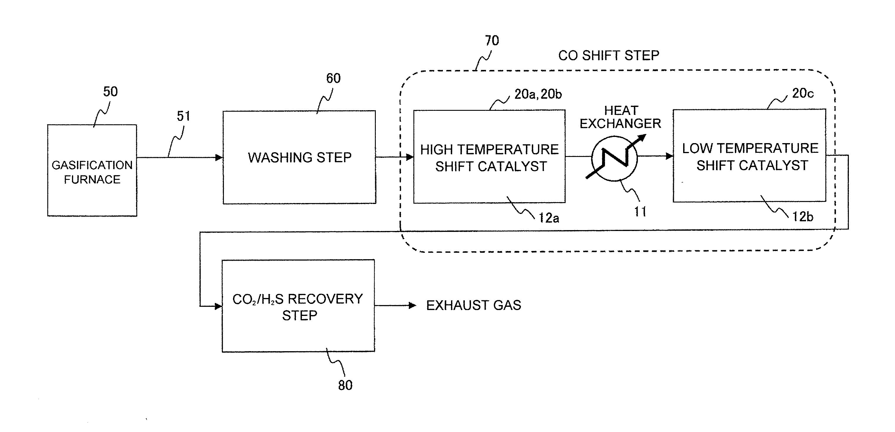
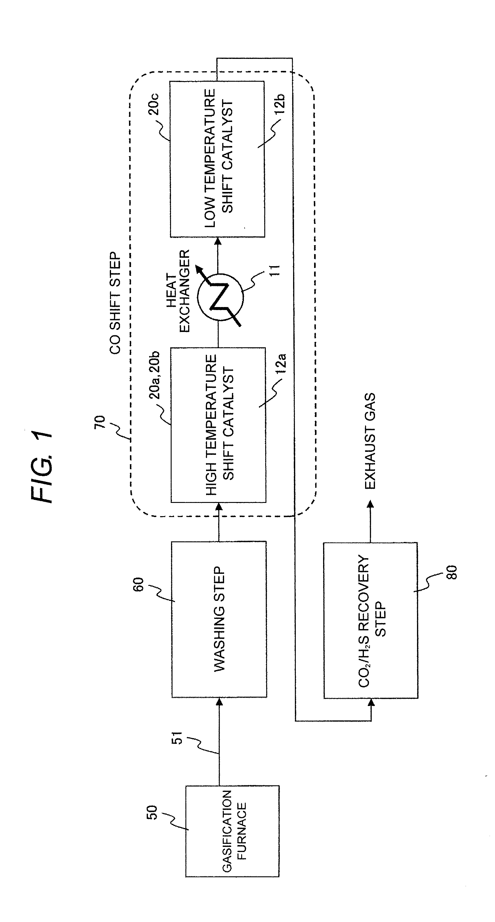
[0043]FIG. 1 shows a schematic flow diagram of a gas purification system for a coal gasifier plant according to a first embodiment of the present invention. In the schematic flow diagram of a gas purification system for a coal gasifier plant according to this embodiment shown in FIG. 1, since water-soluble substances such as a hydrogen halide and ammonia are contained in a product gas 51 which is a coal gas obtained by gasification of coal in a gasifier 50 for gasifying coal, the product gas 51 is scrubbed in a scrubbing step 60 provided downstream of the gasifier 50.

[0044]Thereafter, the product gas 51 scrubbed in the scrubbing step 60 is supplied to a CO shift step 70 provided downstream of the scrubbing step 60, and in this CO shift step 70, C...

second embodiment

[0092]Next, a gas purification method and a gas purification equipment of a coal gasifier plant according to a second embodiment of the present invention will be described with reference to FIGS. 4 and 5.

[0093]Since the basic structure of the gas purification system for a coal gasifier plant according to the second embodiment of the present invention shown in FIG. 4 is in common with that of the gas purification system for a coal gasifier plant according to the first embodiment shown in FIG. 2, description of the structure common in both embodiments is omitted, and only different parts will be described below.

[0094]In the gas purification system for a coal gasifier plant according to this embodiment shown in FIG. 4, what is different from the gas purification system for a coal gasifier plant according to the first embodiment is that a CO2 recycling tube 14 for returning a part of CO2 discharged from the regeneration tower 4 to the upstream of the first shift reactor 20a is provided,...

third embodiment

[0103]Next, a shift catalyst according to a third embodiment of the present invention to be used in a gas purification system for a coal gasifier plant will be described with reference to FIGS. 6 to 11 and Table 1.

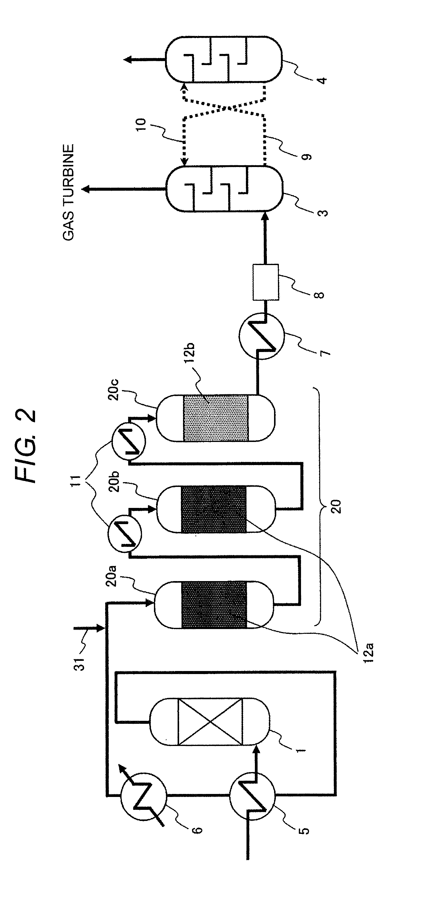
[0104]With respect to the shift catalyst according to the third embodiment of the present invention, which converts CO in a product gas obtained by gasification of coal in the presence of H2S into CO2, test examples showing the operational effect of the catalyst in the case where it is packed as the catalyst in the first shift reactor 20a, the second shift reactor 20b, and the third shift reactor 20c in the gas purification systems for a coal gasifier plant according to the first and second embodiments of the present invention will be described below.

[0105]In this test example, a fixed bed reactor was used for screening a catalyst packed in the first shift reactor 20a, the second shift reactor 20b, and the third shift reactor 20c used in the gas purification systems for a ...


PUM


Abstract

A gas purification method is disclosed for a coal gasifier plant, with which energy loss accompanying recovery of CO2 can be suppressed and soundness of a CO shift catalyst can be maintained in the plant. The method includes a scrubbing step for a product gas produced by gasification of a carbon-containing solid fuel and containing at least CO and H2S to remove water-soluble substances contained in the product gas; a CO shift step to react CO in the product gas after scrubbing with steam using a shift catalyst and converting the gas into CO2 and H2; and a CO2 / H2S recovery to remove CO2 and H2S from the product gas after the CO shift step, wherein the CO shift step is constituted by a multistage shift reactor which includes multiple stages of shift reactors, and shift reactors upstream and downstream have high- and low-temperature shift catalysts, respectively.

Description

BACKGROUND OF THE INVENTION[0001]1. Field of the Invention[0002]The present invention relates to a shift catalyst, which converts CO in a product gas produced by gasification of coal into CO2 in the presence of H2S, and also relates to a gas purification method and a gas purification equipment of a coal gasifier plant, with which CO is efficiently converted into CO2 and H2 using the catalyst.[0003]2. Background Art[0004]A lot of thermal electricity generation plants for generating electricity using a fuel such as coal, petroleum, or a natural gas have been conventionally operated. Among these, a technique relating to an Integrated Coal Gasification Combined Cycle (IGCC), in which coal whose reserves is high and therefore enabling stable supply also in future is used as a fuel, and coal in a gasifier is first gasified, and then, a product gas produced by the gasification of the coal is used as a fuel for generating electricity has attracted attention recently.[0005]Further, amid conc...

Claims


Application Information

Patent Timeline
IPC IPC(8): B01J23/883C01B3/58C01B32/50
CPCB01J21/063B01J23/883B01J23/8877C01B3/16C01B2203/0288C01B2203/0415C01B2203/0465C10J2300/093C10J2300/165C10J2300/1675C10K1/003C10K1/08C10K1/101C10K3/04Y02P20/52
Inventor SASAKI, TAKASHIAKIYAMA, TOMOKO
Owner HITACHI LTD
Why Eureka
Try Eureka