Radiation generating apparatus and radiation imaging apparatus

Inactive Publication Date: 2014-06-05
CANON KK
View PDF9 Cites 162 Cited by
  • Summary
  • Abstract
  • Description
  • Claims
  • Application Information

AI Technical Summary

Benefits of technology

[0010]According to the present invention, shielding performance of an unnecessary radiation can be ensured, and heat of the target can be effectively radiated. Further, a thermal conducting member having a lower density than a radiation shielding member is used, thereby allowing an entire radiation generating apparatus to be reduced in weight. This allows radiation imaging with a large

Problems solved by technology

However, generally, generation efficiency of a radiation is extremel

Method used


Image

  • Radiation generating apparatus and radiation imaging apparatus
  • Radiation generating apparatus and radiation imaging apparatus
  • Radiation generating apparatus and radiation imaging apparatus

Examples


example 1

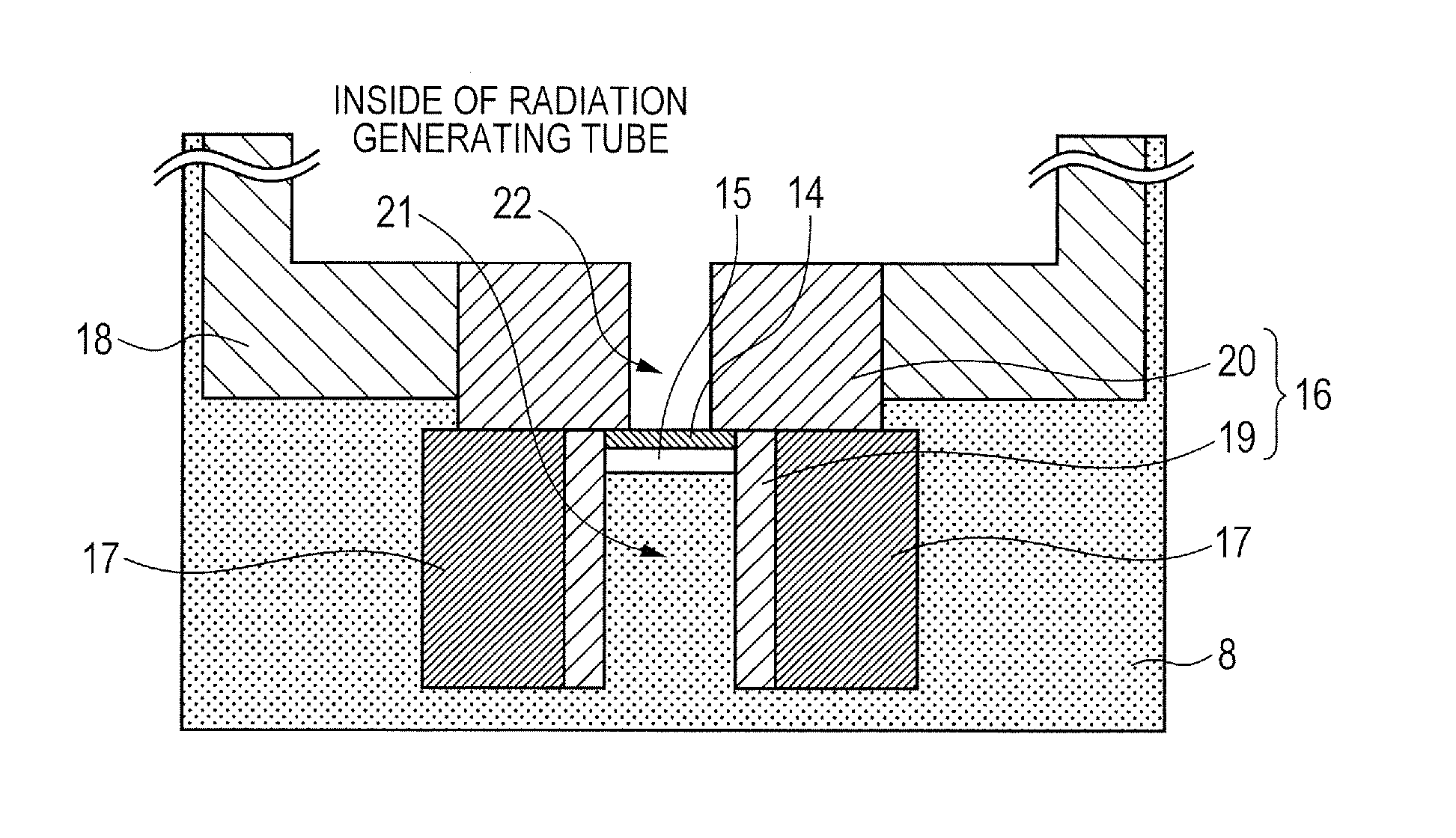
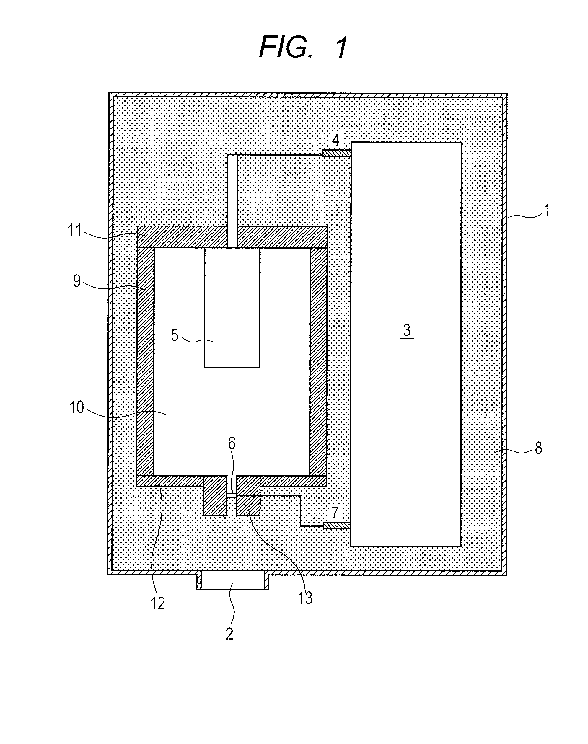
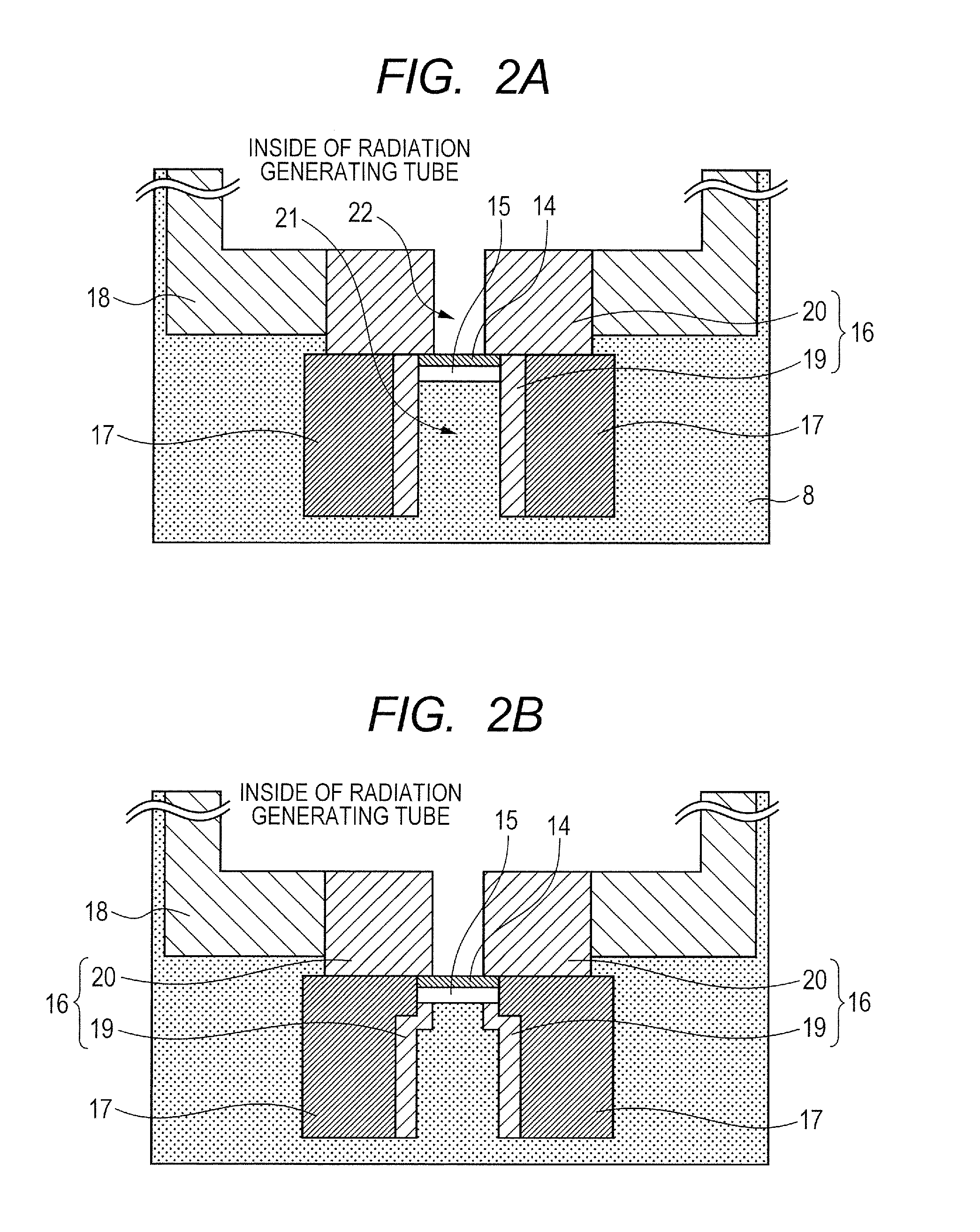
[0043]As illustrated in FIG. 2A, tungsten was selected as the shielding member 16 including the first shielding member 19 and the second shielding member 20 integrally formed, and copper was selected as the thermal conducting member 17. The thermal conducting member 17 was secured by brazing to an outer peripheral side of a portion of the shielding member 16 having a protruding portion protruding from the second window 15 toward the first window 2. As the insulating fluid 8, insulation oil including mineral oil was used. As a voltage control system, a neutral grounding system was used. As the electron emitting source 5, a tungsten filament was used and heated by an unshown heating unit to emit an electron. The emitted electron was accelerated to high energy by electron beam trajectory control by distribution of potentials caused by voltages applied to an extraction electrode and a lens electrode, and a voltage Va applied between the electron emitting source 5 and the target 14 and c...

example 2

[0044]As illustrated in FIG. 2B, in this example, the first shielding member 19 and the second shielding member 20 are separately placed, and the thermal conducting member 17 is placed on the outer peripheral side of the first shielding member 19 so as to be partially in direct contact with the second window 15. This example has a similar configuration to that of Example 1 except for this point. A part of heat generated in the second window 15 is directly transferred to the thermal conducting member 17 without via the first shielding member 19, thereby further increasing a speed of heat radiation.

example 3

[0045]This example is similar to Example 1 except that molybdenum is selected as the shielding member 16, and aluminum is selected as the thermal conducting member 17, and sheet molybdenum is used as the target 14. This example is different from Example 1 in using an anode grounding system as a voltage control system. To set 50[V] to an extraction electrode, 3000 [V] to a lens electrode, and Va in the anode grounding system to 50 [kV], the voltage of the target 14 was set to +50 [kV] and the voltage of the electron emitting source 5 was set to 0 [kV].


PUM


Abstract

A radiation generating apparatus includes: an envelope 1 having a first window 2 through which a radiation is transmitted; and a radiation tube 10 being held within the envelope 1, and having a second window 15 which is arranged in opposition to the first window 2, and through which the radiation is transmitted; and a radiation shielding member 16 thermally connected to the second window 15, having a radiation transmitting hole 21 arranged in communication with the second window 15, and having a protruding portion protruding from the second window 15 toward the first window 2. A thermal conducting member 17 having a higher thermal conductivity rather than that of the radiation shielding member 16 is connected to the protruding portion of the radiation shielding member 16. The radiation generating apparatus can shield an unnecessary radiation and cool a target with a simple structure and is entirely reduced in weight.

Description

TECHNICAL FIELD [0001]The present invention relates to a radiation generating apparatus used for non-destructive X-ray imaging in the fields of medical devices and industrial devices, and a radiation imaging apparatus using the radiation generating apparatus.BACKGROUND ART [0002]Generally, a radiation tube accelerates an electron emitted from an electron emitting source at high voltage to irradiate a target with the electron to generate a radiation such as an X-ray. The radiation generated at this time is emitted in all directions. PTL 1 discloses a transmission X-ray generation apparatus in which X-ray shielding members are placed on an electron incident side and an X-ray emission side of a target to shield an unnecessary X-ray.[0003]In order to generate a radiation suitable for radiation imaging, a high voltage needs to be applied between an electron emitting source and a target to irradiate the target with an electron beam with high energy. However, generally, generation efficien...

Claims


Application Information

Patent Timeline
IPC IPC(8): G01N23/04H01J35/12H01J35/16
CPCH01J2235/186H05G1/025H01J2235/166H05G1/04G01N23/04H01J2235/122H01J35/16H01J35/12H01J35/186A61B6/00H05G1/02
Inventor YANAGISAWA, YOSHIHIROAOKI, SHUJITAMURA, MIKIUEDA, KAZUYUKINOMURA, ICHIRO
Owner CANON KK
Why Eureka
Try Eureka