Multi-band multiplexing intra-cavity gas sensing system and method
a gas sensing system and intra-cavity technology, applied in the field of sensing and detecting technology, can solve the problem of limited applicability in terms of gas types, and achieve the effect of significant scientific value and economic benefits
- Summary
- Abstract
- Description
- Claims
- Application Information
AI Technical Summary
Benefits of technology
Problems solved by technology
Method used
Image
Examples
embodiment 1
Preferable Technical Scheme for a Multi-Band Multiplexing Intra-Cavity Gas Sensing System
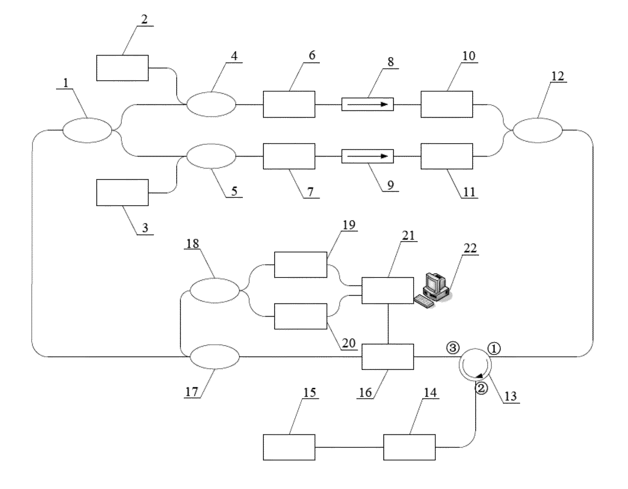
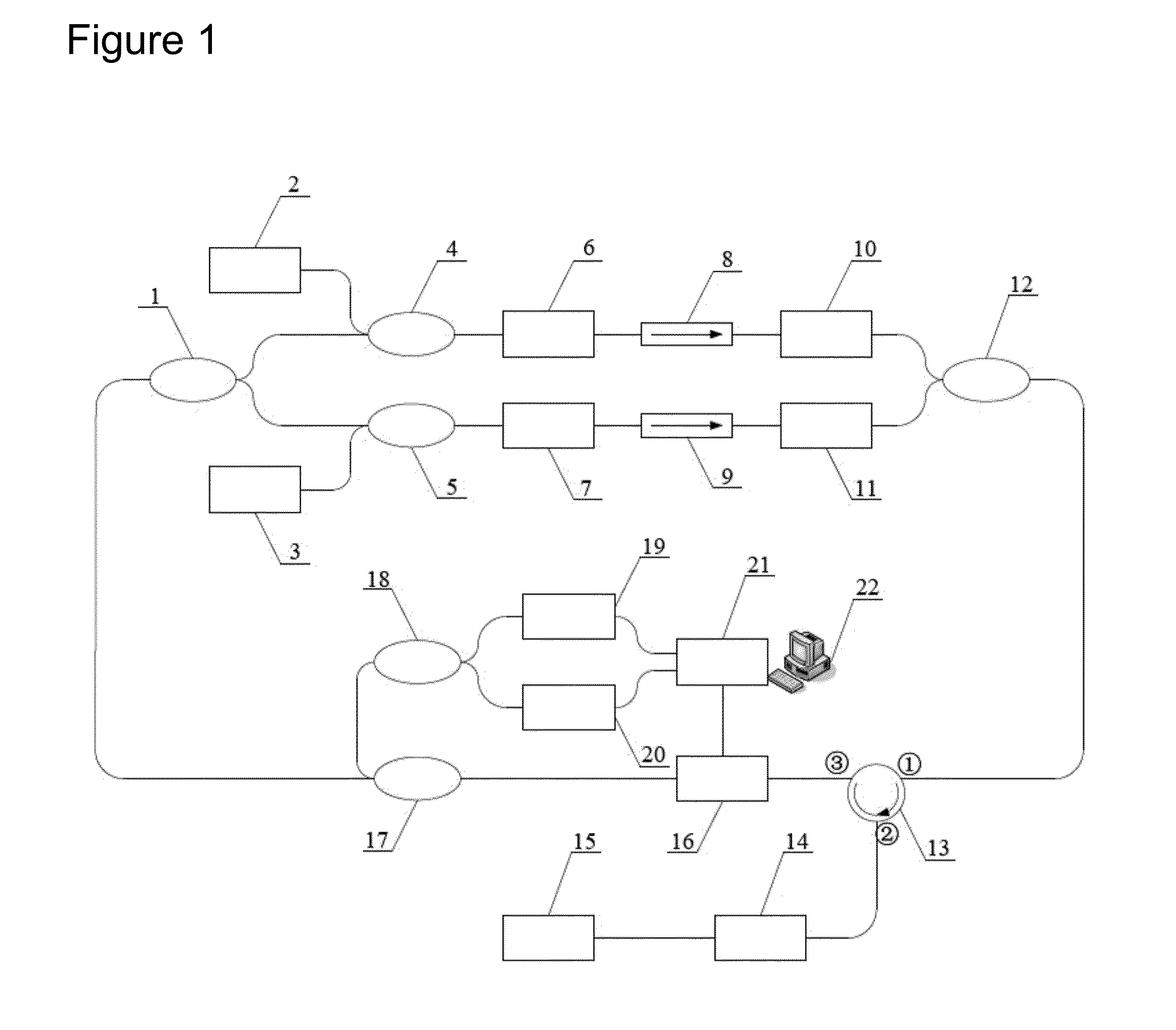
[0037]The embodiment of the multiple-band multiplexing intra-cavity gas sensing system is described with examples of optical fibers doped with erbium and ytterbium, respectively. The schematic construction of the system is illustrated in FIG. 1. The system consists of a beam splitter, a pump light source, a wavelength division multiplexer, two optical fibers (the optical fibers doped with erbium and ytterbium respectively), an optical isolator, a tunable optical attenuator, a beam combiner, an optical circulator, a gas cell, an optical reflective mirror, a F-P tunable optical filter, an optical coupler, an optical detector, a data acquisition module and a computer.
[0038]A gain path 1 is constructed by the first pump light source with a wavelength of 980 nm, the first wavelength division multiplexer 4 (980 nm / 1550 nm), an optical fiber doped with erbium 6, the first optical isolator 8 (1550 nm), ...
embodiment 2
Preferable Technical Scheme for Demodulation of a Multiple-Band Aliasing Intra-Cavity Gas Sensing System
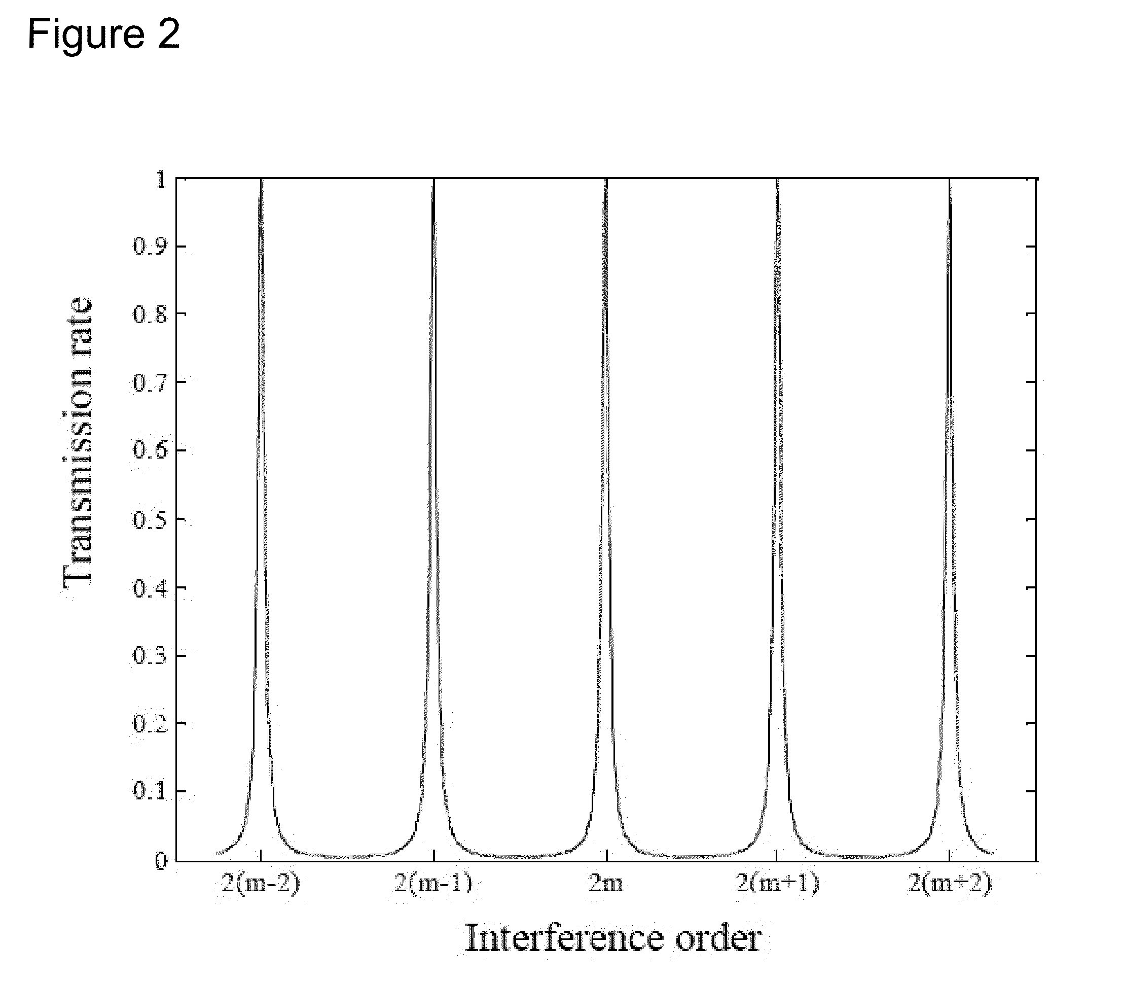
[0042]The embodiment of the demodulation of a multiple-band aliasing intra-cavity gas sensing system will be described with examples of a multiple-band aliasing intra-cavity gas sensing system of the optical fibers doped with erbium and ytterbium respectively. As shown in FIG. 1, a systematic construction is illustrated. The voltage waveform output by the analog output port of the data acquisition module connected with the computer is used for driving the F-P tunable optical filter so as to achieve scanning of transmission wavelength. The two analog input ports are intended to capture optical voltage value output by the two ways of optical detectors. All the analog input and output ports work at the same time, thus making sure that there is definite correspondence between the wavelength of laser output by the system and optical power value.
[0043]Driven by linear voltage, the entir...
embodiment 3
Preferable Technical Scheme for Expandability of a Multiple-Band Aliasing Intra-Cavity Gas Sensing System
[0049]The present system has strong expandability as shown in FIG. 5. The construction of the gain path is illustrated in FIG. 6. A number of new gain paths can be added by increasing number of the beam splitter and ports of the beam combiner. The gain band of the new gain path should meet three conditions as shown below: (1) it should be different mutually from the gain band of the existed system gain path; (2) the gain bandwidth should be smaller than the free spectrum range of the F-P tunable optical filter; (3) the interval of it with the gain band of the existed system gain path should be larger than the free spectrum range of the F-P tunable optical filter. Further, the system should also be provided with an optical detector for detection of laser signals output by newly added gain path, said laser signals being acquired synchronously by the data acquisition module and proc...
PUM
| Property | Measurement | Unit |
|---|---|---|
| wavelength | aaaaa | aaaaa |
| wavelength ranges | aaaaa | aaaaa |
| wavelength ranges | aaaaa | aaaaa |
Abstract
Description
Claims
Application Information
 - R&D
- Intellectual Property
- Life Sciences
- Materials
- Tech Scout
- Unparalleled Data Quality
- Higher Quality Content
- 60% Fewer Hallucinations
Browse by: Latest US Patents, China's latest patents, Technical Efficacy Thesaurus, Application Domain, Technology Topic, Popular Technical Reports.
© 2025 PatSnap. All rights reserved.Legal|Privacy policy|Modern Slavery Act Transparency Statement|Sitemap|About US| Contact US: help@patsnap.com


