
Multi-band multiplexing intra-cavity gas sensing system and method

a gas sensing system and intra-cavity technology, applied in the field of sensing and detecting technology, can solve the problem of limited applicability in terms of gas types, and achieve the effect of significant scientific value and economic benefits

Inactive Publication Date: 2015-01-13
TIANJIN UNIV
View PDF11 Cites 2 Cited by
  • Summary
  • Abstract
  • Description
  • Claims
  • Application Information

AI Technical Summary

Benefits of technology

The present invention is a multi-band based multiplexing sensing system for intra-cavity gas that uses rare-earth doped fibers to detect various types of gases by using optical fiber active intra-cavity sensing. The system covers gain bands of various doped ions, which significantly extends the wavelength scanning range of the system. The system has strong expandability, allowing for the detection of more types of gases and the separation of gas absorption spectrum curves on the wavelength domain. The expanding method involves increasing the port number of beam splitters and optical combiners and adding a gain path between the output port of the first beam splitter and the input port of the optical combiner, as well as a certain number of optical detectors.

Problems solved by technology

However, the gain band of one optical fiber doped with rare earth elements covers only part of the bandwidth, with limited applicability in terms of gas types.

Method used


Image

  • Multi-band multiplexing intra-cavity gas sensing system and method
  • Multi-band multiplexing intra-cavity gas sensing system and method
  • Multi-band multiplexing intra-cavity gas sensing system and method

Examples


embodiment 1

[0037] Preferable Technical Scheme for a Multi-Band Multiplexing Intra-Cavity Gas Sensing System

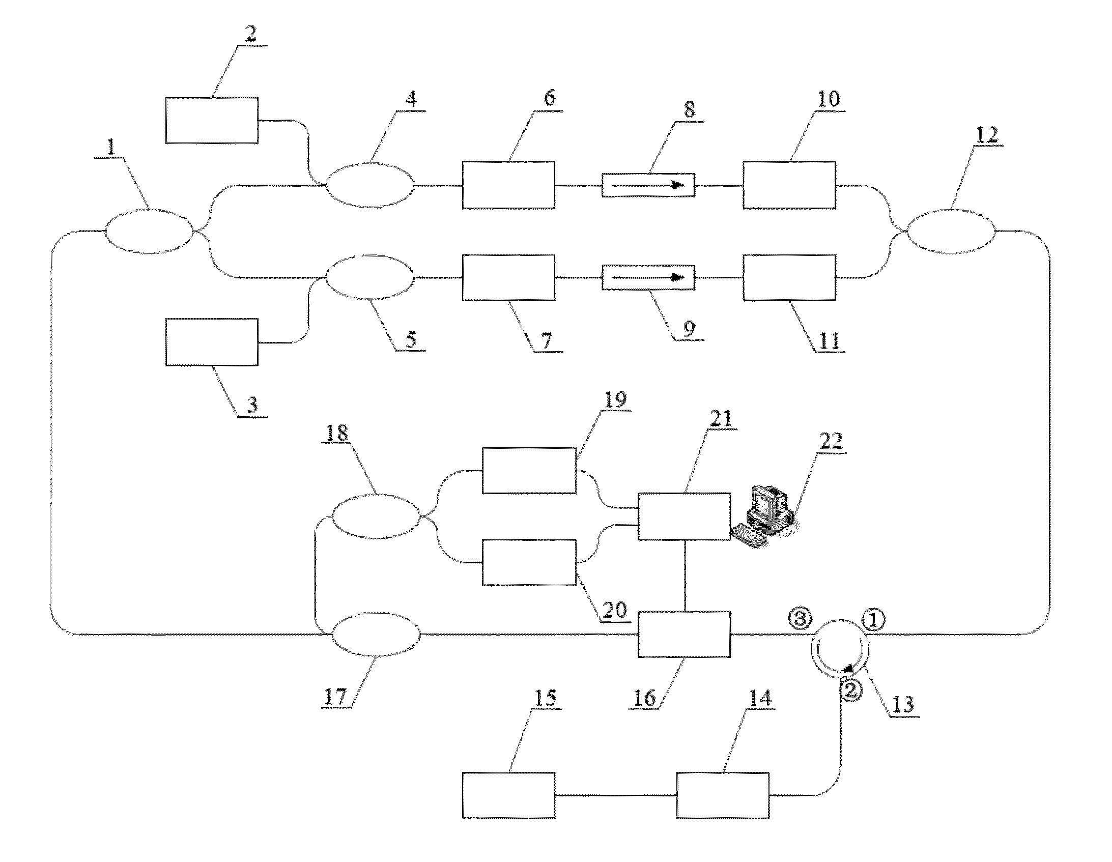
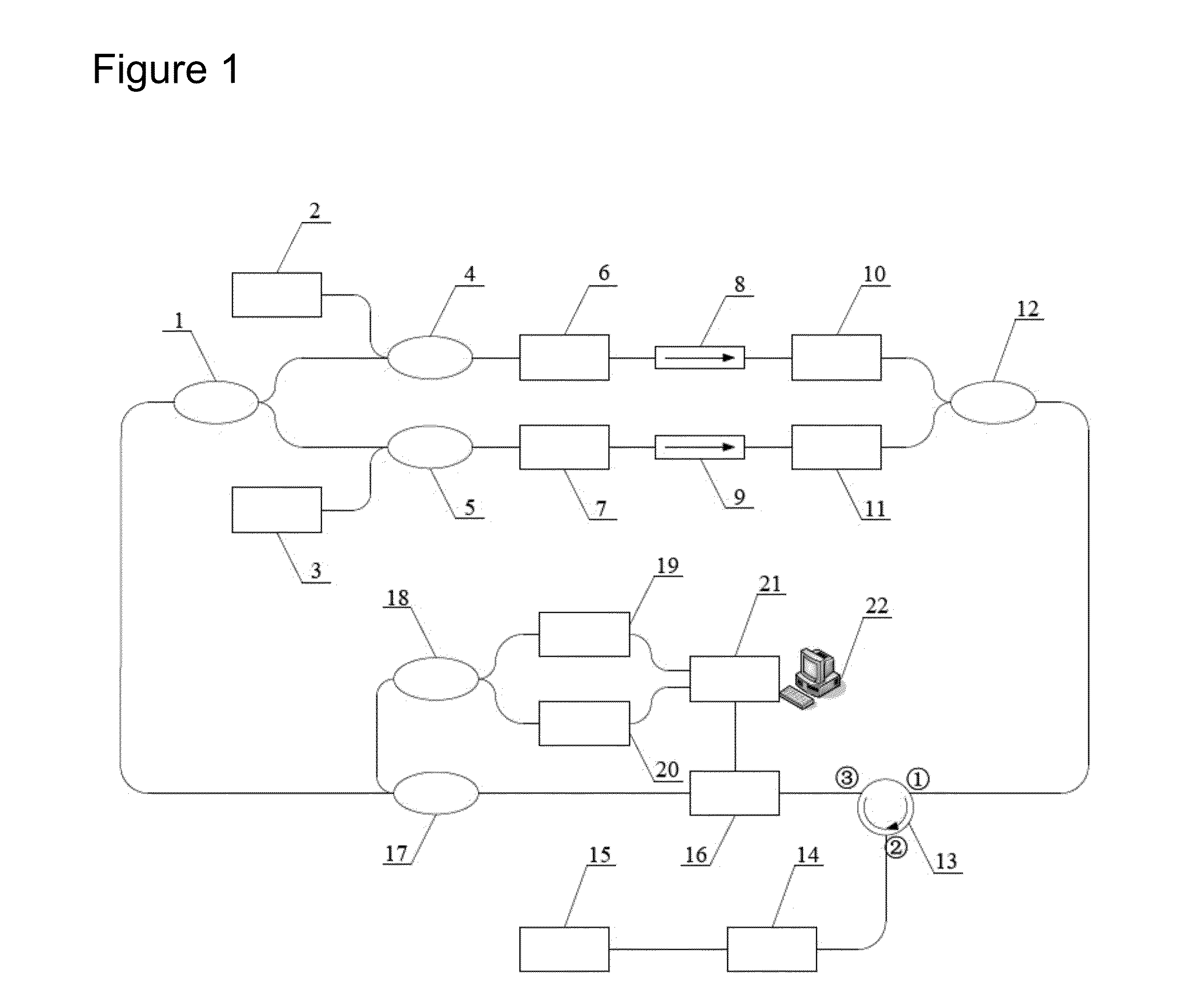
[0038]The embodiment of the multiple-band multiplexing intra-cavity gas sensing system is described with examples of optical fibers doped with erbium and ytterbium, respectively. The schematic construction of the system is illustrated in FIG. 1. The system consists of a beam splitter, a pump light source, a wavelength division multiplexer, two optical fibers (the optical fibers doped with erbium and ytterbium respectively), an optical isolator, a tunable optical attenuator, a beam combiner, an optical circulator, a gas cell, an optical reflective mirror, a F-P tunable optical filter, an optical coupler, an optical detector, a data acquisition module and a computer.

[0039]A gain path 1 is constructed by the first pump light source with a wavelength of 980 nm, the first wavelength division multiplexer 4 (980 nm / 1550 nm), an optical fiber doped with erbium 6, the first optical isolator 8 (155...

embodiment 2

[0043] Preferable Technical Scheme for Demodulation of a Multiple-Band Aliasing Intra-Cavity Gas Sensing System

[0044]The embodiment of the demodulation of a multiple-band aliasing intra-cavity gas sensing system will be described with examples of a multiple-band aliasing intra-cavity gas sensing system of the optical fibers doped with erbium and ytterbium respectively. As shown in FIG. 1, a systematic construction is illustrated. The voltage waveform output by the analog output port of the data acquisition module connected with the computer is used for driving the F-P tunable optical filter so as to achieve scanning of transmission wavelength. The two analog input ports are intended to capture optical voltage value output by the two ways of optical detectors. All the analog input and output ports work at the same time, thus making sure that there is definite correspondence between the wavelength of laser output by the system and optical power value.

[0045]Driven by linear voltage, th...

embodiment 3

[0054] Preferable Technical Scheme for Expandability of a Multiple-band Aliasing Intra-cavity Gas Sensing System

[0055]The present system has strong expandability as shown in FIG. 5. The construction of the gain path is illustrated in FIG. 6. A number of new gain paths can be added by increasing number of the beam splitter and ports of the beam combiner. The gain band of the new gain path should meet three conditions as shown below: (1) it should be different mutually from the gain band of the existed system gain path; (2) the gain bandwidth should be smaller than the free spectrum range of the F-P tunable optical filter; (3) the interval of it with the gain band of the existed system gain path should be larger than the free spectrum range of the F-P tunable optical filter. Further, the system should also be provided with an optical detector for detection of laser signals output by newly added gain path, said laser signals being acquired synchronously by the data acquisition module a...


PUM

PropertyMeasurementUnit
wavelengthaaaaaaaaaa
wavelength rangesaaaaaaaaaa

Abstract

Disclosed is a multi-band multiplexing intra-cavity gas sensing system and method. The system consists of a laser resonant cavity subsystem, a gas sensing subsystem and a detection-demodulation subsystem. The laser resonant cavity subsystem consists of the first beam splitter, two ways of gain paths composed of a pump light source, a wavelength division multiplexer, a rare earth doped fiber, an optical isolator and a tunable optical attenuator, a beam combiner and an F-P tunable optical filter. The gas sensing subsystem consists of a gas cell and an optical reflective mirror. The detection-demodulation subsystem consists of an optical coupler, the second beam splitter, two optical detectors, a data acquisition module and a computer. In this invention, different rare-earth doped fibers are multiplexing into one system, in order to cover more maser bands of different rare earth, which greatly expands the scanning range of wavelength, and is capable of detecting various gases simultaneously. New gain paths can be added to the system, to further expand the scanning range of wavelength. Hence, the present invention has strong expandability.

Description

FIELD OF THE INVENTION[0001]The present invention pertains to field of sensing and detecting technology.BACKGROUND OF THE INVENTION[0002]Online monitoring, indicating and controlling flammable, explosive, toxic and hazardous gases have been one of the important issues to be solved urgently for the high risk industries, such as coal mining, petroleum mining, chemistry and thermal power generation. In addition, a system to monitor and control toxic and hazardous gases is expected for maintaining a clean environment, with the improvement of living standards of human being. As a result, the development of a system for sensing and monitoring hazardous gases is essential and becomes a key topic in the field of sensing technology.[0003]Gas detection method working with optical fiber sensing technique, especially near infrared absorption spectrum quantitative detection, has developed rapidly in the last two decades. As a novel optical fiber gas detection method provided in this invention, o...

Claims


Application Information

Patent Timeline
Patent Type & Authority Patents(United States)
IPC IPC(8): G01N21/00G01N21/35G01N21/39
CPCG01N21/39G01N21/3504G01N2021/391
Inventor LIU, KUNLIU, TIEGENJIANG, JUNFENGLIANG, XIAO
Owner TIANJIN UNIV
Learn More