
Solar plant

a solar energy and plant technology, applied in semiconductor lasers, lighting and heating equipment, instruments, etc., can solve the problems of solar energy posing, loss of excess energy transported by photons, and loss of heat energy

Inactive Publication Date: 2014-07-24
ABENGOA SOLAR NEW TECH SA
View PDF0 Cites 4 Cited by
  • Summary
  • Abstract
  • Description
  • Claims
  • Application Information

AI Technical Summary

Benefits of technology

The patent describes a new solar plant that uses laser devices to capture and convert solar energy into electricity. The laser devices are designed to have a very small beam angle, which allows the energy to be directed to a receiver with high efficiency. The laser beams can be transmitted through lightguides or directly through the atmosphere using plane mirrors. The lightguides can be directed to the receiver so that they do not affect adjacent receptor locations, resulting in a uniform incidence on the receiver tubes. The invention solar plant can transform solar energy into electricity with higher yields than current solar energy plants and efficiently exploit the width of the solar spectrum.

Problems solved by technology

The exploitation of solar energy poses a number of challenges.
One of them is the capture and concentration of that solar energy, an issue that is widely researched, developed and applied today.
Another major challenge is the transformation of solar energy into electrical energy.
However, it has the disadvantage of being unmanageable, and a wavelength range exists above which photovoltaic cells are not capable of converting all the energy from photons into electrical energy, and below which the excess of energy transported by the photon is lost as heat.
It does not present the disadvantage mentioned above in relation to photovoltaic technology, but it has other problems discussed below.
However, central receiver plants suffer from the so-called cosine effect (effect of decreasing effective reflecting area of the mirror due to the angle formed by the rays relative to the normal for said reflecting surface), spillover in the receiver, losses from transmittance and other phenomena that limit their efficiency when compared to the potential of photovoltaic technology.
One of the issues that makes this technology so expensive is its having to support a heavy cantilever engine at the centre of the concentrator.
Guiding concentrated sunlight with minimal losses from the catchment area to the processing area is another big challenge.
Moreover, the challenge is twofold: on one hand to develop lightguides with materials capable of transmitting the full spectral width of sunlight, and the other to use lightguides that are compatible with advanced collectors (non-imaging optics) and allow high concentrations, that is, lightguides of a high numerical aperture.
Additionally, these guides do not allow for efficient guiding of the solar spectrum over distances of tens of meters.
The conclusion is that, in the best case, these fibres do not efficiently transmit a significant portion of the solar spectrum (UV, visible and part of the near-IR) representing over 40% of the accumulated energy in the solar spectrum.
Moreover, the chromatic scattering of these fibres can be flexibly adjusted by design adapted to their geometry, making obtainable values that are unattainable using conventional fibre optic technology.
Thus, triple junction cells consisting of InGaAs, Ge and InGaP semiconductors have current efficiencies on the order of 39%, but there are wavelength ranges in which it is not capable of converting photons into electrical energy.
However, they have the downside of being manufactured from materials incapable of transmitting the full spectral width of the sun with losses—in dB / km—to make this technology feasible.
There are some state of the art examples of such converters, but they do not allow for achieving high enough efficiencies or maintaining high optical concentrations, mainly due to the direction of the light emitted after the conversion—it has no preferred direction or directions.

Method used


Image

  • Solar plant
  • Solar plant
  • Solar plant

Examples


Embodiment Construction

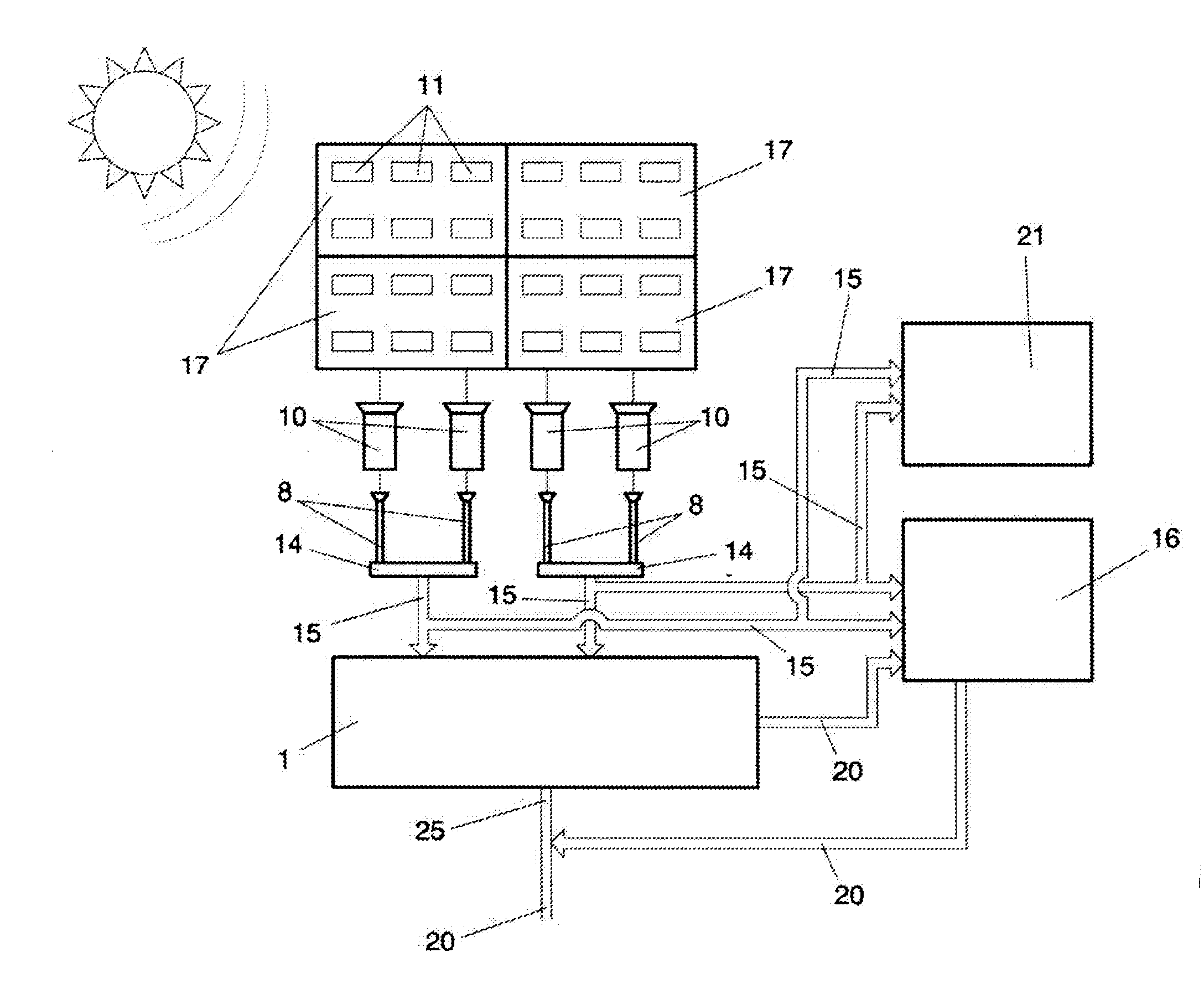
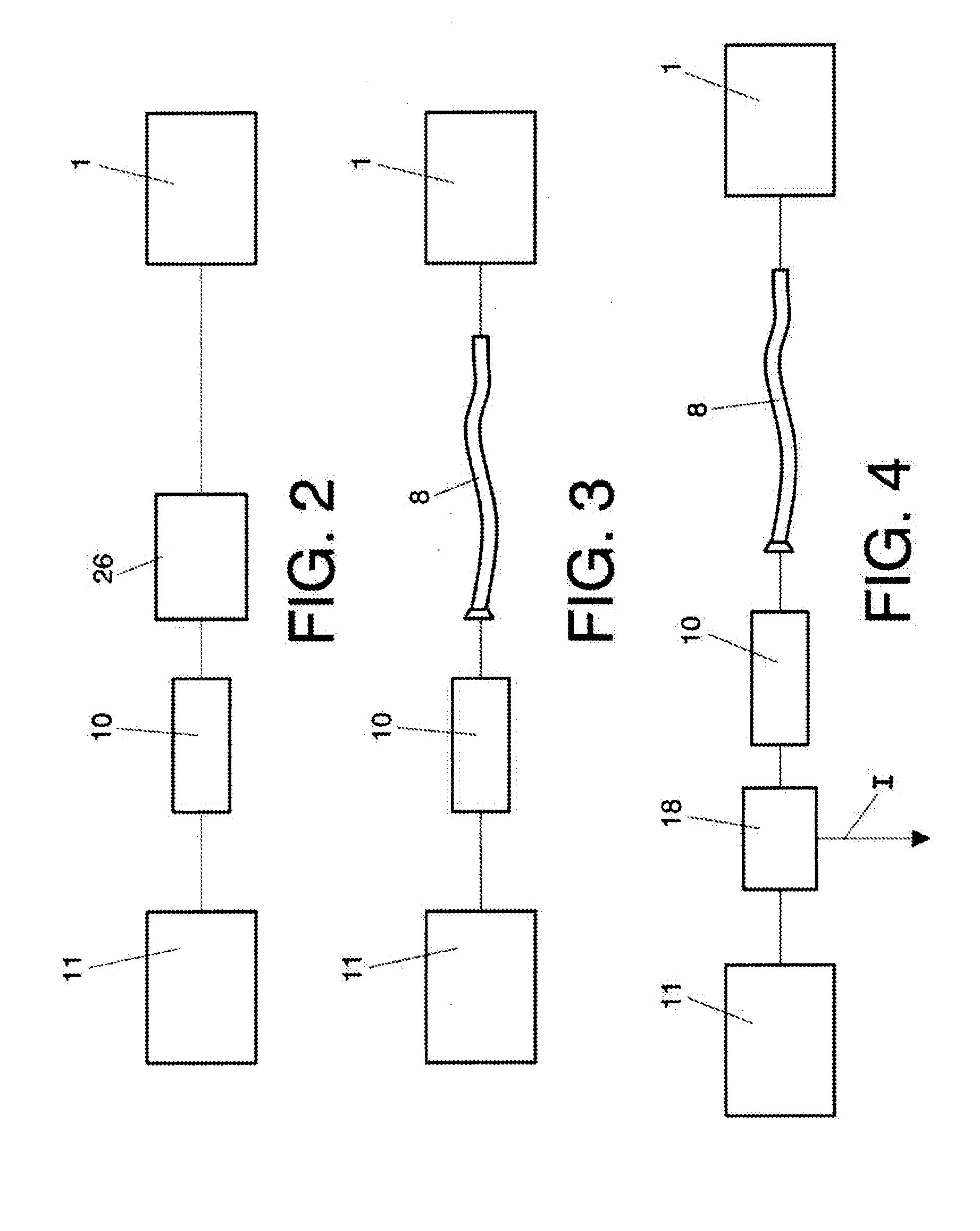
[0033]This invention solves the technical problem posed through a solar plant that allows for maximised exploitation of solar radiation. The solar plant of the invention comprises the following elements:[0034]At least one solar collector equipped with a concentrator, said solar collector adapted to collect solar radiation and concentrate that solar radiation in the concentrator;[0035]At least one solar laser device, as a solar converter, where the laser device is adapted to receive (directly or indirectly) concentrated radiation from the concentrators in the collectors and transform said concentrated radiation into laser radiation, and[0036]A receiver adapted to receive radiation from the laser and transform it into thermal energy (heating a heat transfer fluid) or directly into electricity using the photoelectric effect; and / or a solar reactor adapted to obtain solar fuel, for instance hydrogen directly from water at temperatures up to 2000° C. by use of third substances (zinc or o...


PUM


Abstract

A solar plant enabling transformation of solar energy exploiting most of the solar spectrum with very efficient yields, including: at least one solar collector including a concentrator, configured to collect and concentrate solar radiation in the concentrator; a solar laser device to transform radiation received from the concentrators into laser radiation; a receiver and / or a solar reactor configured to receive radiation from the laser device and transform it into another form of energy; and can include flexible lightguides or plane mirrors to transport the radiation received from the laser device to the solar reactor and / or receiver, and photovoltaic cells interspersed among the collectors and laser devices to transform the concentrated radiation into electricity and allow radiation not transformed to pass to the laser devices.

Description

PURPOSE OF THE INVENTION[0001]The present invention may be included within the field of solar technology. The purpose of the invention pertains to a solar plant which enables the transformation a larger portion of incoming solar radiation spectrum into electrical or thermal energy.BACKGROUND OF THE INVENTION[0002]The exploitation of solar energy poses a number of challenges. One of them is the capture and concentration of that solar energy, an issue that is widely researched, developed and applied today. In this respect, the challenge of solar plants is: to maximise the C / Cmax ratio of concentrator collectors (where C is the concentration and Cmax=1 / sine (half acceptance) is the theoretical maximum concentration), to minimise geometric losses—cosine effect, shadows and blockages among trackers—, optical and heat losses, and to lower the plant costs at levels that make the technology competitive in relation to other energy sources. Importantly, maximising concentration allows us to r...

Claims


Application Information

Patent Timeline
IPC IPC(8): H01L31/052F03G6/06F24S20/20
CPCF03G6/06H01L31/052Y02E10/52H01S3/0915H01L31/0543H01L31/0547G02B6/02314H01L31/055H01S3/005H01S3/06704H01S3/06741H01S3/08059H01S3/23Y02E10/46H01S5/026
Inventor NUNEZ BOOTELLO, JUAN PABLOGALLAS TORREIRA, MANUEL
Owner ABENGOA SOLAR NEW TECH SA
Learn More