Method and device for finishing work pieces

Inactive Publication Date: 2014-08-14
MAG IAS
View PDF9 Cites 9 Cited by
  • Summary
  • Abstract
  • Description
  • Claims
  • Application Information

AI Technical Summary

Problems solved by technology

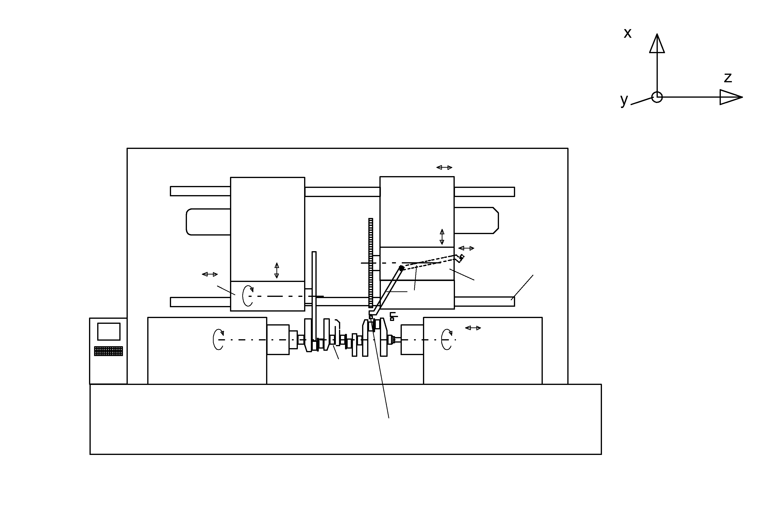
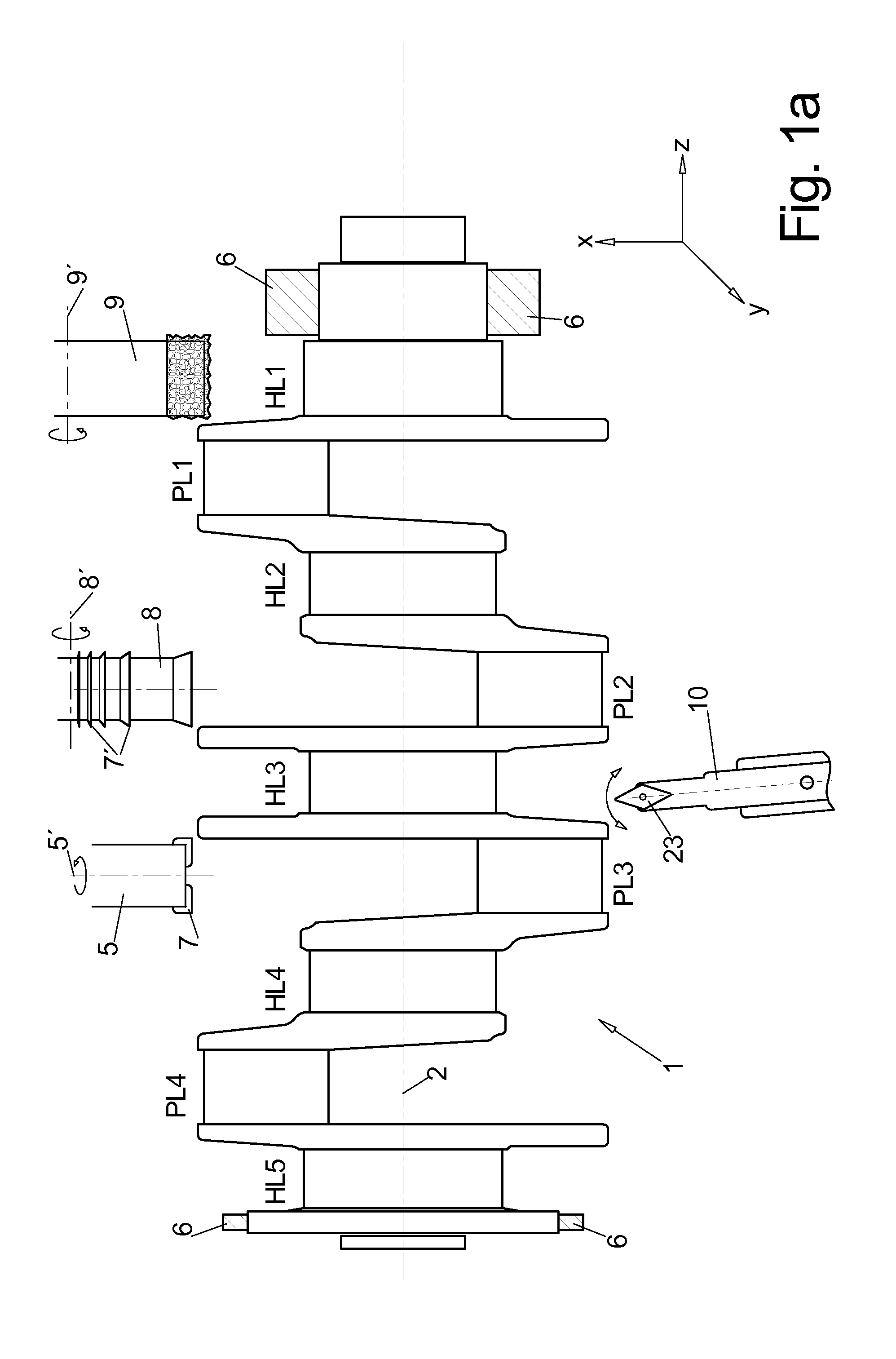
Crank shafts in particular crank shafts for car engines with a high number of cylinders are known to be work pieces that are instable during machining and thus difficult to work on.
Thus maintaining required tolerances for these parameters is limited by the available machining methods and also by the instability of the work piece and the machining forces.
This causes renewed warping of the crank shaft which had to be compensated by grinding and finishing.
Omitting the rough machining step by providing the forming typically forging precise enough so that only fine machining is subsequently required has not been successful so far at least in series production.
Disadvantages of removing material through wet grinding however are:the grinding sludge caused by the added coolant-lubricant is difficult to dispose of;there is a latent risk of an explosion due to the oil included in the coolant-lubricant e.g. during CBN grinding;the amount of coolant-lubricant used is much greater for grinding than for chip removing machining methods, since the coolant-lubricant is additionally used for removing grinding dust out of a surface of the grinding disc through high pressure spraying which requires large amounts of energy;in spite of all the above the risk of overheating the work piece is very high.
Prior optimization attempts, however, do not sufficiently consider the options and in particular the possible combinations of the new machining methods with a defined edge and also with a non defined edge and without edge which meanwhile are also provided in variants for hard machining, thus for machining hardened work piece surfaces and can thus be used at the work piece after hardening.during turn-milling, thus milling at a rotating work piece fine adjustable (precise down to one μ meter) cutting plates are used in particular for external milling, thus milling with a milling bit that is disc shaped and serrated at its circumference, wherein the cutting plates are arranged for example on wedge systems of the base element of the milling bit, wherein the cutting plates are adjustable precisely enough so that also for 20-50 teeth on a milling bit excellent circularity and diameter precision at the work piece can be achieved.for an orthogonal milling bit acceptable material removing performance is meanwhile achieved using 1 to 10 cutting edges at the face without influencing surface quality to an excessively negative extent since the cutting edges can not only be adjusted or ground quite well relative to one another but since additionally, and this also applies to an external milling bit the cutting edges are made for example from finest grain hard metal with a very fine grit structure.
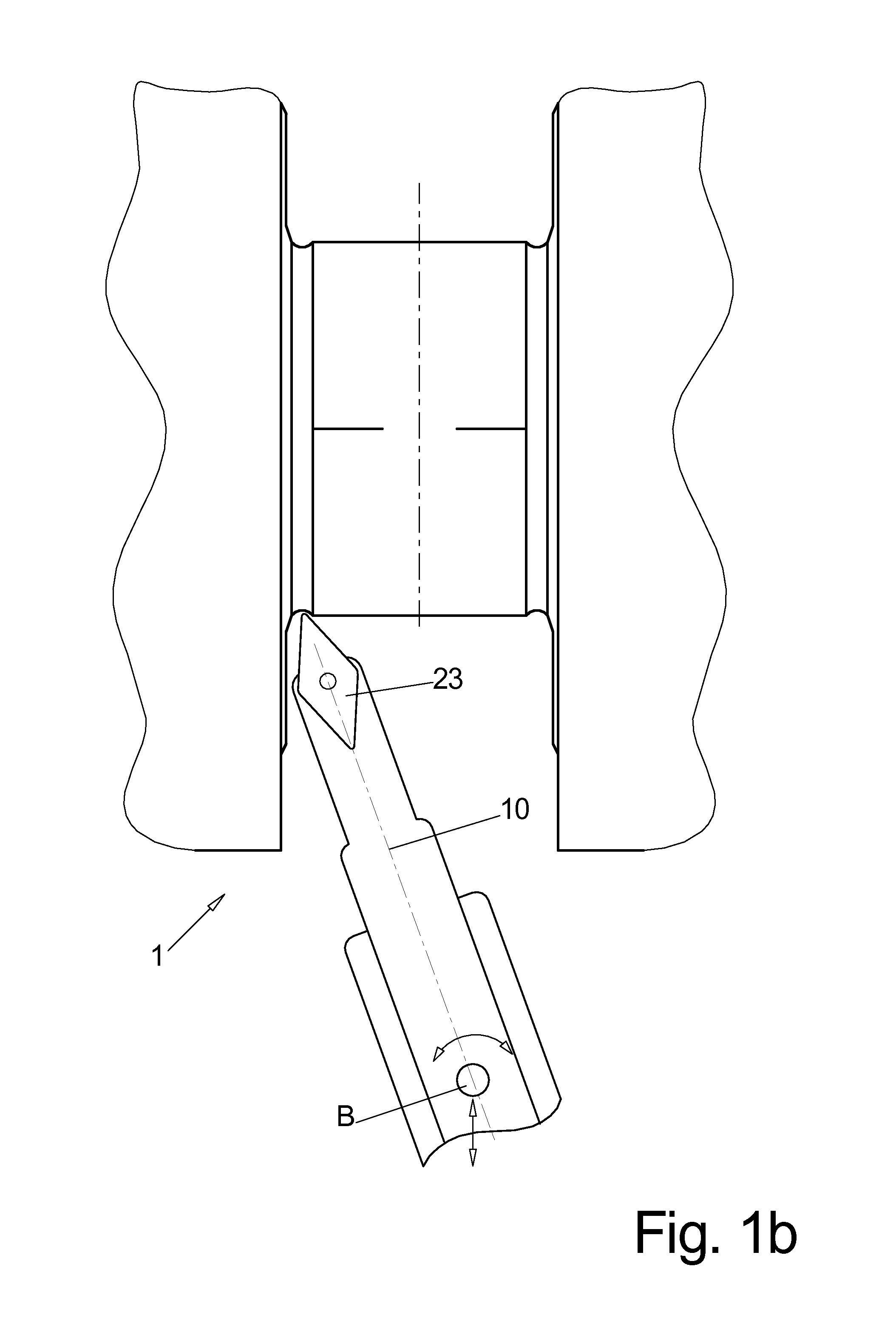
This helps in particular to partially overcome the previous mutual exclusivity of hardness and elasticity of the cutting edge.during fine longitudinal turning of the bearing locations there was a problem so far in that turning tools with different elbows were required for turning left and right corner portions and therefore typically a non avoidable step of 10-30μ meters was provided in the transition portion of the two machining locations wherein the step could not be efficiently removed through finishing alone since due to the relatively imprecise self guiding support of the finishing tool a material removal has to be performed for removing the step that is many times greater which requires a large amount of finishing time.

Method used


Image

  • Method and device for finishing work pieces
  • Method and device for finishing work pieces
  • Method and device for finishing work pieces

Examples


Embodiment Construction

a) TECHNICAL OBJECT

[0043]Thus it is an object of the invention to reduce fine machining of the work pieces recited supra to provide usability in particular after hardening, in particular to reduce the number of process steps.

b) SOLUTION

[0044]The object is achieved by the characterizing features of claims 1, 2 and 18. Advantageous embodiments can be derived from the dependent claims.

[0045]Thus, it is an object of the present invention to machine the work pieces recited supra and in particular their bearings after chip removing rough machining which achieves a precision of 0.1 mm and possible subsequent hardening which causes additional warping.

[0046]The subsequently recited processing steps typically relate to the same machining location.

[0047]According to the invention it is presumed that a first finishing step is required after coarse machining, wherein the first finishing step is used for achieving dimensional precision and a second finishing step is used for achieving the respect...


PUM

PropertyMeasurementUnit
diameteraaaaaaaaaa
diameteraaaaaaaaaa
cutting speedsaaaaaaaaaa

Abstract

In order to shorten a process chain for chip removing processing of a crank shaft after coarse machining and after hardening according to the invention a combination of turn milling or single point milling is proposed as a first step and a subsequent line machining step through finishing or electro chemical etching is proposed.

Description

I. FIELD OF THE INVENTION[0001]The invention relates to a method and a device for machining rotation symmetrical and also non rotation symmetrical components, in particular crank shafts and mass production, in particular bearing surfaces (of crank pin bearings and also journal bearings) of crank shafts to a useable condition, thus the condition when the crank shaft can be installed in an engine without additional material removal at the bearing surfaces.[0002]Thus bearing surfaces are enveloping surfaces, thus a width of the bearing, and also the so called transom surfaces, thus the faces adjacent to the bearing width which are used for example for axial support.II. BACKGROUND OF THE INVENTION[0003]Crank shafts in particular crank shafts for car engines with a high number of cylinders are known to be work pieces that are instable during machining and thus difficult to work on. Determining dimensional compliance of a finished crank shaft is primarily provided besides axial bearing wi...

Claims


Application Information

Patent Timeline
Patent Type & Authority Applications(United States)
IPC IPC(8): B23P13/02B23Q39/02B23P23/04
CPCB23H3/00B23C3/06B23D37/005B23B5/18B23P13/00B23K26/0084B23P23/04B24B5/42B23K2201/005B23P2700/07B23K26/0009B23K2203/04B23H2300/10B23H9/00B23P13/02B23Q39/02B23K2103/50B23K26/355B23K26/0006B23K2101/005B23K2103/04F16C3/08Y10T29/17Y10T29/49286B23B2215/20B23B2220/445B23H5/06
Inventor SCHREIBER, LEOWEBER, MATTHIAS
Owner MAG IAS
Why Eureka
Try Eureka