Sliding bearing and image forming apparatus

a technology of sliding bearings and image forming apparatus, which is applied in the direction of sliding contact bearings, electrographic processes, instruments, etc., can solve the problems of increased cost, increased uniformity, and complex structure of the groove ball bearings serving as bearings for the heated roller of the fuser device in the image forming apparatus described above, so as to reduce the lubricating power and improve the surface precision. , the effect of improving the stability of the friction torqu

Inactive Publication Date: 2014-08-14
NTN CORP
View PDF4 Cites 17 Cited by
  • Summary
  • Abstract
  • Description
  • Claims
  • Application Information

AI Technical Summary

Benefits of technology

[0049]As discussed above, the sliding bearing according to the present invention is a radial sliding bearing comprising an inner ring and an outer ring, one of the inner ring and the outer ring made of a melt-cast metal have a concavely curved surface along part of the axial direction, and the other ring comprises an article molded from a resin composition, the article having a convexly curved surface along part of the axial direction that contacts and slides against the concavely curved surface, and the inner ring and the outer ring relatively rotate without contacting each other apart from contacting parts of the convexly curved surface and the concavely curved surface. Because one of the inner ring and the outer ring is made of melt-cast metal, reductions in lubricating power due to wear shedding of metal particulate or base oil being drawn into holes can be prevented. In addition, the concavely curved surface has better surface precision compared to cases in which the ring is made of sintered metal, and friction torque is more stable. Moreover, there is no limit upon the rotational directions of the inner and outer rings, allowing identical sliding bearings to be used at both ends of the roller or shaft.
[0050]In addition, the bearing comprises two parts, the inner ring and the outer ring, and thus has fewer parts and a simpler structure than a ball bearing. This allows for easy manufacture, enables reductions in manufacturing steps and assembly time, and allows for low-cost provision. In addition, one of the inner ring or the outer ring being an article molded from a resin composition yields self-insulating properties and the like not found in ball bearings, eliminating the need to provide a separate insulating sleeve or the like. In addition, it is easy to replace the sliding bearing alone, as in the case of a ball bearing.
[0051]Because the concavely curved surface and the convexly curved surface contact and slide against each other, the material and surface roughness of the counterpart roller or shaft do not affect friction torque or wear levels, unlike resin sliding bearings that directly slide a...

Problems solved by technology

This arrangement is in order to prevent heat escaping through the ball bearings at both ends when the heated roller is being heated, which can lead to an uneven temperature distribution along the axial direction of the heated roller.
However, the deep-groove ball bearings serving as bearings for the heated roller of the fuser device in the image forming apparatus described above are complex in structure and expensive to manufacture.
The necessity of the resin insulating sleeve in order to prevent disruptions in temperature distribution uniformity further increases costs.
Moreover, bending of the support shaft due to errors in mounting precision in the support shaft of the heated roller or moment loads carries the risk of damaging the bearings.
However, such resin sliding bearings have low load capacity compared to ball bearings, and 10 times or more the level of friction torque.
As a result, the capacity of the actuating motor must be increased when the bearings are used in an image forming apparatus such as a multifunction machine, printer, or FAX machine, leading to an overall increase in expense.
Such bearings are also highly sensitive to the material and surface roughness of the rollers against which they slide.
A rough roller sliding surface will increase friction torque and wear levels, and, if the roller is of a soft metal, the resin sliding bearing will cause friction damage in the roller, leading to...

Method used


Image

  • Sliding bearing and image forming apparatus
  • Sliding bearing and image forming apparatus
  • Sliding bearing and image forming apparatus

Examples


examples 1-8

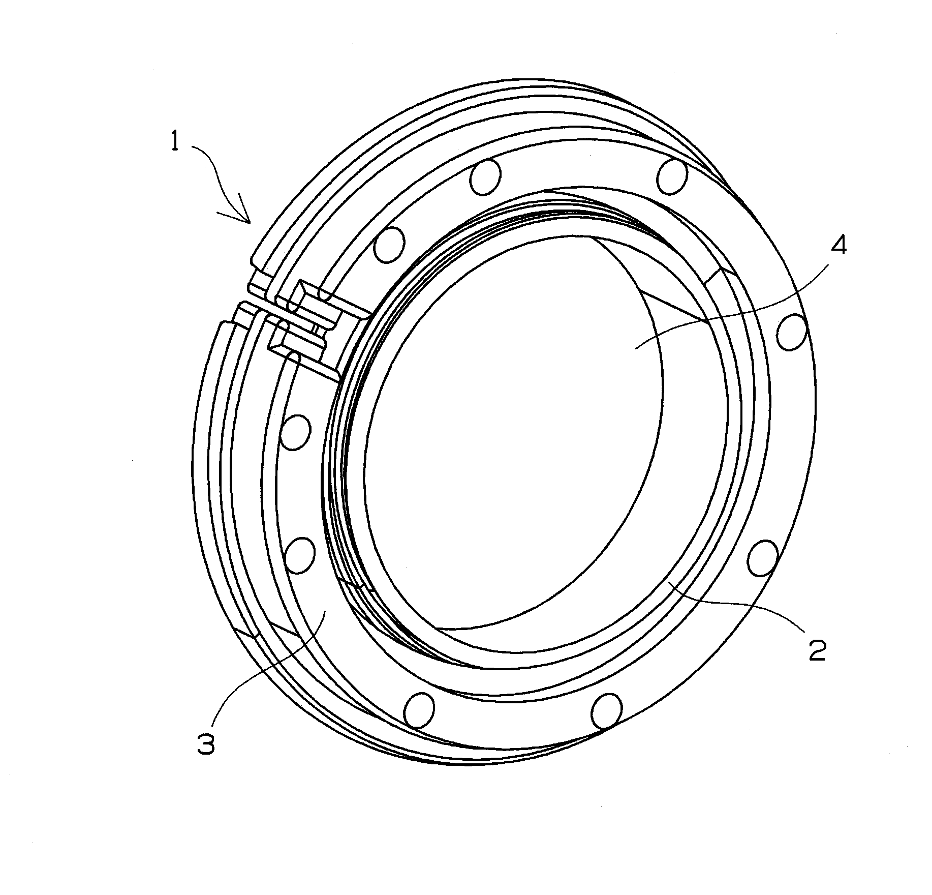
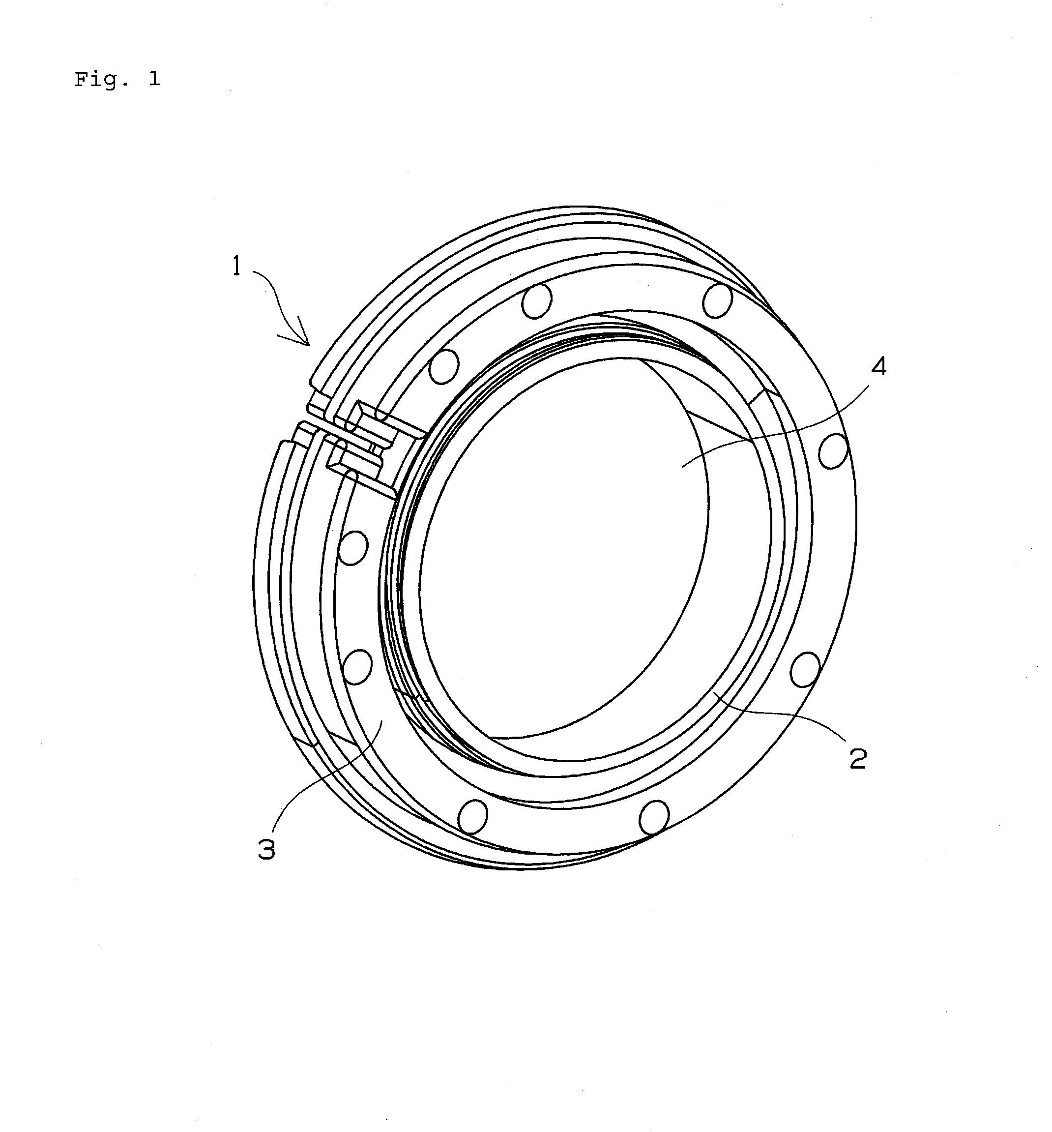
[0195]Using an injection-molded resin article for the outer ring and a machined (turned, ground) article of melt-cast metal as the inner ring, grease was interposed between the inner and outer rings according to the arrangement shown in FIG. 1 to create a test bearing. The primary dimensions were as follows.

Inner ring: φ 25×φ 27.5 (outer circumference concave portion)×7 mm

Outer ring: φ 27.78 (inner circumference convex portion)×φ 37×7 mm

Sliding contact radius: φ 27.5 mm

[0196]The material, concavely curved surface machining method, and surface roughness of the inner ring and the material, composition, and grease type of the outer ring are shown in Table 1. The inner rings of examples 1-8 are repurposed inner rings for 6805 ball bearings, with finished products being used as the inner rings of examples 1-3 and 6-8 and unfinished products being used as the inner rings of examples 4 and 5. 0.3 g grease was applied to the entire sliding surfaces (both sides) of the inner and outer rings,...

examples 9 through 13

[0210]Sliding bearings for use in food product machine applications were rated. The test bearing used for these examples was the sliding bearing having the configuration shown in FIG. 1, the outer ring being an injection-molded resin article, and the inner ring being a repurposed inner ring for a 6805 ball bearing and being a machined article (surface roughness Ra 0.03 μm) made of SUS 440C stainless steel. The primary dimensions were as follows.

Inner ring: φ 25×φ 27.5 (outer circumference concave portion)×7 mm

Outer ring: φ 27.78 (inner circumference convex portion)×φ 37×7 mm

Sliding contact radius: φ 27.5 mm

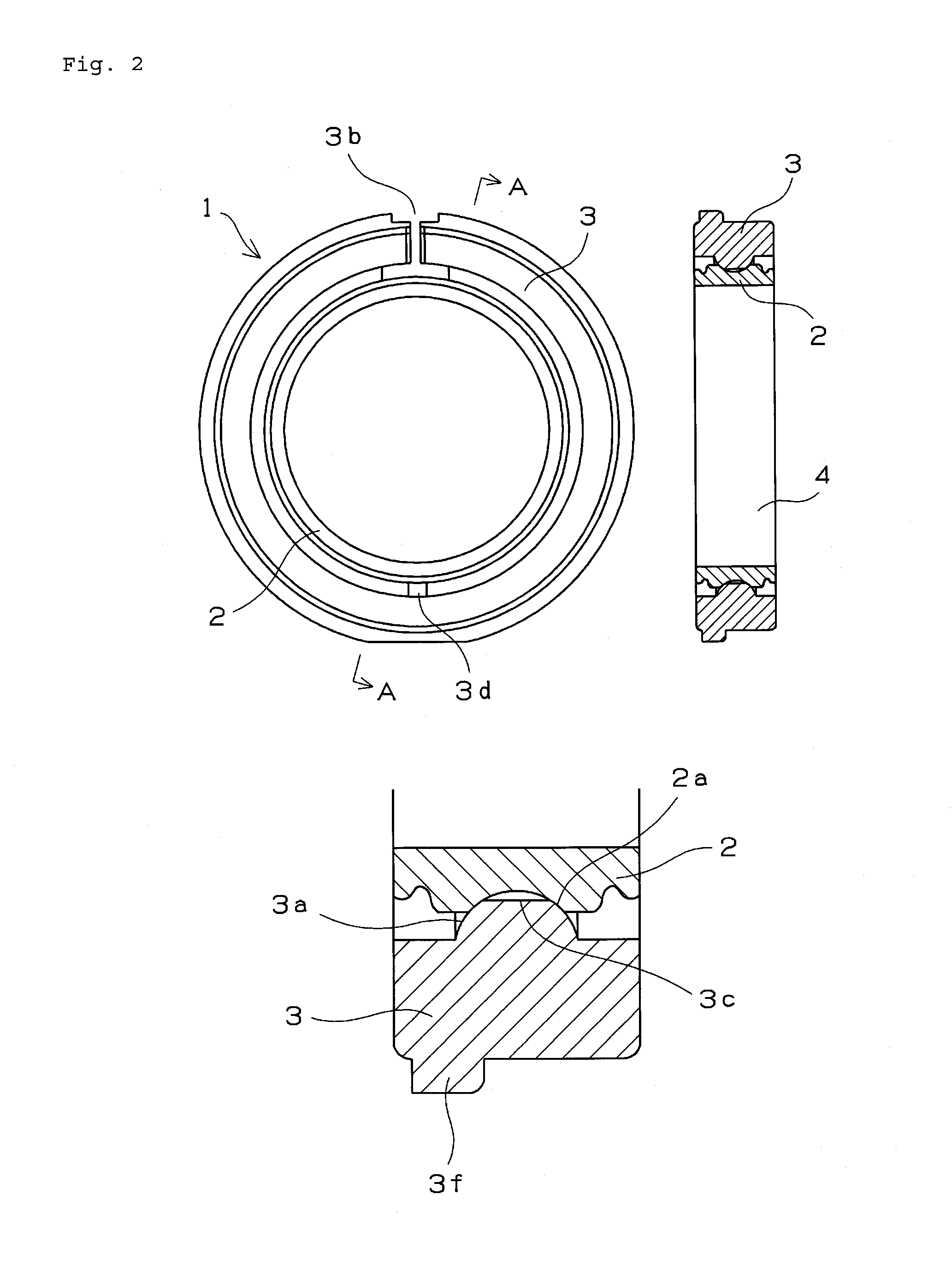
[0211]The convex portions on the inner circumferences at the joints in the outer rings were not formed within ranges of ±10° with respect to the joints, and the two ends of the convex portions formed 45° angles with respect to the tangent lines of the inner circumferences of the outer ring, as shown in FIGS. 2 and 5. The radius of curvature of the concavely curved surface on the o...


PUM

PropertyMeasurementUnit
Angleaaaaaaaaaa
Surface roughnessaaaaaaaaaa
Electrical resistivityaaaaaaaaaa

Abstract

Provided is a sliding bearing that has a simple, easy-to-manufacture structure, does not require an insulating sleeve or the like, is not affected by the material or surface roughness of a roller against which the bearing slides, exhibits low friction torque and low wear, tolerates moment loads, and is easy to replace; as well as an image forming apparatus using the bearing. The sliding bearing is a radial sliding bearing provided with a sliding bearing (1), an inner ring (2), and an outer ring (3), the inner ring (2) is made of melt-cast metal and the outer ring (3) being constituted by an article molded from a resin composition, the inner ring (2) comprising a concavely curved surface (2a) on part of the axial direction of the outer circumference and a bearing hole (4) for mating with a support shaft on the inner circumference, the outer ring (3) comprising a convexly curved surface (3a) that contacts and slides against the concavely curved surface (2a) on the outer circumference of the inner ring (2) along part of the axial direction of the inner circumference, and the inner ring (2) and the outer ring (3) relatively rotating without contacting each other apart from the contact between the convexly curved surface and the concavely curved surface.

Description

TECHNICAL FIELD[0001]The present invention relates to a sliding bearing, and, in particular, to a sliding bearing used to support a roller (heated roller), such as a fuser roller or pressure roller, or shaft of a fuser unit in an image forming apparatus such as a photocopier, multifunction machine, printer (laser printer, inkjet printer, or the like), or fax machine, onto support various types of rollers and shafts in a developer unit, photosensitive unit, transfer unit, paper ejector unit, paper feeder unit, or the like. The present invention also relates to a sliding bearing used in a belt-driving unit for an ink cartridge carriage in an inkjet printer. The present invention also relates to an image forming apparatus using these sliding bearings. The present invention also relates to a sliding bearing for supporting a rotary shaft of a food product machine.BACKGROUND ART[0002]Generally, an image forming apparatus involves causing toner to adhere to a latent electrostatic image, fo...

Claims


Application Information

Patent Timeline
IPC IPC(8): F16C33/20F16C33/10F16C33/12
CPCF16C13/02F16C23/045G03G21/1647G03G15/167G03G15/2053G03G15/757F16C33/102F16C2370/38F16C2208/78F16C2208/66F16C2208/60F16C2208/52F16C2208/40F16C2208/36F16C2208/32F16C2204/72F16C2204/70F16C2204/66F16C2202/32F16C33/208F16C33/201F16C33/121F16C2220/04F16C2204/52F16C2240/54F16C2204/60F16C17/02F16C17/022F16C17/22F16C23/046F16C33/124F16C2240/30F16C2324/16
Inventor ISHII, TAKUYAFUJITSUKA, IKUMAHATTORI, KEIHIROSE, KAZUOFUKUZAWA, SATORU
Owner NTN CORP
Why Eureka
Try Eureka