Laminated common-mode choke coil

a common-mode choke coil and common-mode technology, applied in the direction of inductance, mutual inductance, fixed transformers, etc., can solve the disadvantageous increase of normal-mode signal insertion loss, difficult to increase the coupling degree between the primary coil and the secondary coil, and common-mode noise current attributed to asymmetry of the signal line. , to achieve the effect of increasing the coupling degree between the primary coil and the secondary coil, and increasing the degree of coupling stray capa

Active Publication Date: 2014-10-16
MURATA MFG CO LTD
View PDF3 Cites 22 Cited by
  • Summary
  • Abstract
  • Description
  • Claims
  • Application Information

AI Technical Summary

Benefits of technology

[0012]According to various preferred embodiments of the present invention, the degree of coupling between the primary coil and the secondary coil is significantly increased without causing an increase in stray capacitance between the primary coil and the secondary coil. Hence, a compact common-mode choke coil with which the loss of normal-mode signals is small particularly at high frequency bands, and with which common-mode noise is not prone to be converted to normal-mode signals is provided.

Problems solved by technology

However, practically speaking, particularly with a signal line for a high-speed interface, common-mode noise current attributed to asymmetry of the signal line occurs.
However, it is difficult to increase the degree of coupling between the primary coil and the secondary coil just by aligning the primary coil and the secondary coil simply in the laminated direction in the lamination element.
When the degree of coupling between the primary coil and the secondary coil is low, the insertion loss of the normal-mode signals is disadvantageously increased.
On the other hand, when the primary coil and the secondary coil are closely disposed to each other in order to increase the degree of coupling, the capacitance occurring between the primary coil and the secondary coil (stray capacitance) is disadvantageously increased.
When this capacitance becomes great, the differential impedance of the common-mode choke coil is reduced, thus failing to match with the impedance of the balanced line.
Further, with the structure in which the primary coil and the secondary coil are aligned in the laminated direction in the lamination element, misalignment of the formation position of coil patterns or misalignment in laminating the sheets occurs as a problem in the process.
Further, when the common-mode choke is mounted on a printed circuit board, the balance between the capacitance between the primary coil and the ground conductor and the capacitance between the secondary coil and the ground conductor is lost because of problems in the structure such as a difference between the coils in the coupling amount with the ground conductor on the printed circuit board.
This makes it impossible to secure symmetry between the primary coil and the secondary coil, and common-mode noise is converted into normal-mode signals.
However, since the magnetic substance has relatively great frequency dependence, the loss of normal-mode signals particularly at high frequency bands tends to become great.
Further, a full coupling value cannot be obtained between the primary coil and the secondary coil particularly at high frequency bands, and the loss of normal-mode signals tends to become great.

Method used


Image

  • Laminated common-mode choke coil
  • Laminated common-mode choke coil
  • Laminated common-mode choke coil

Examples


first preferred embodiment

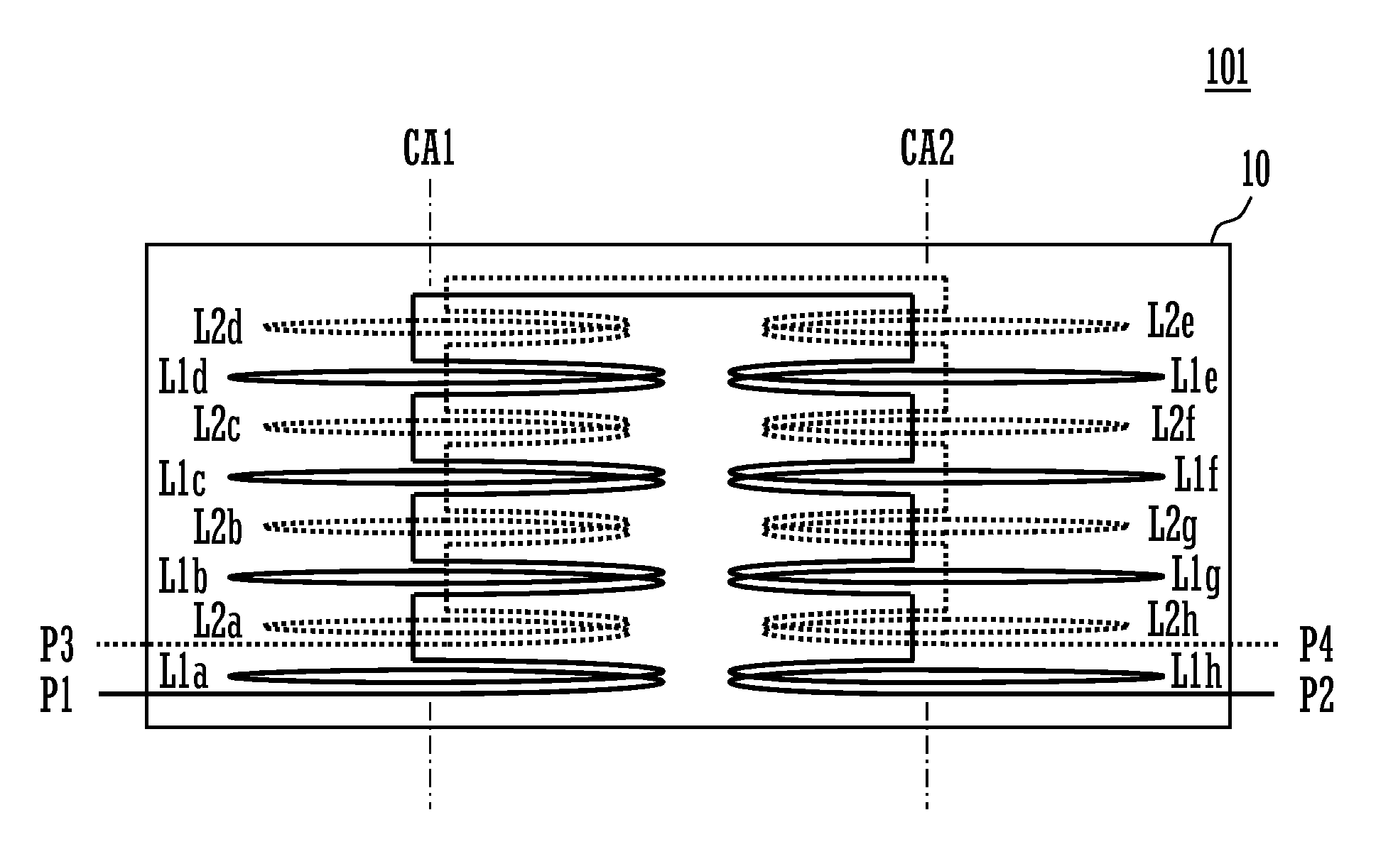
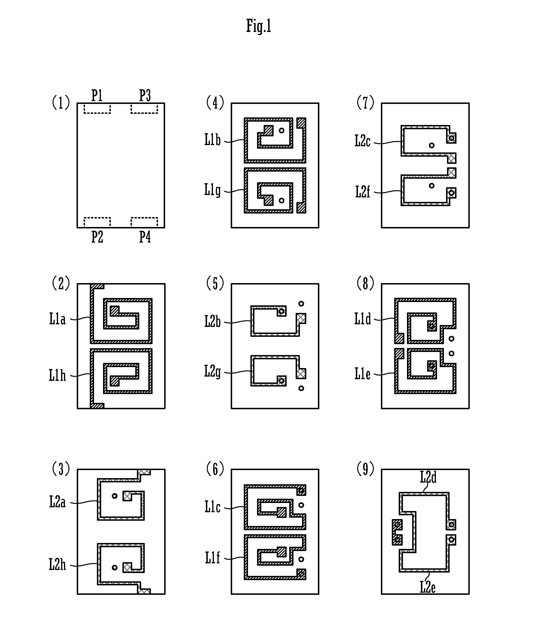
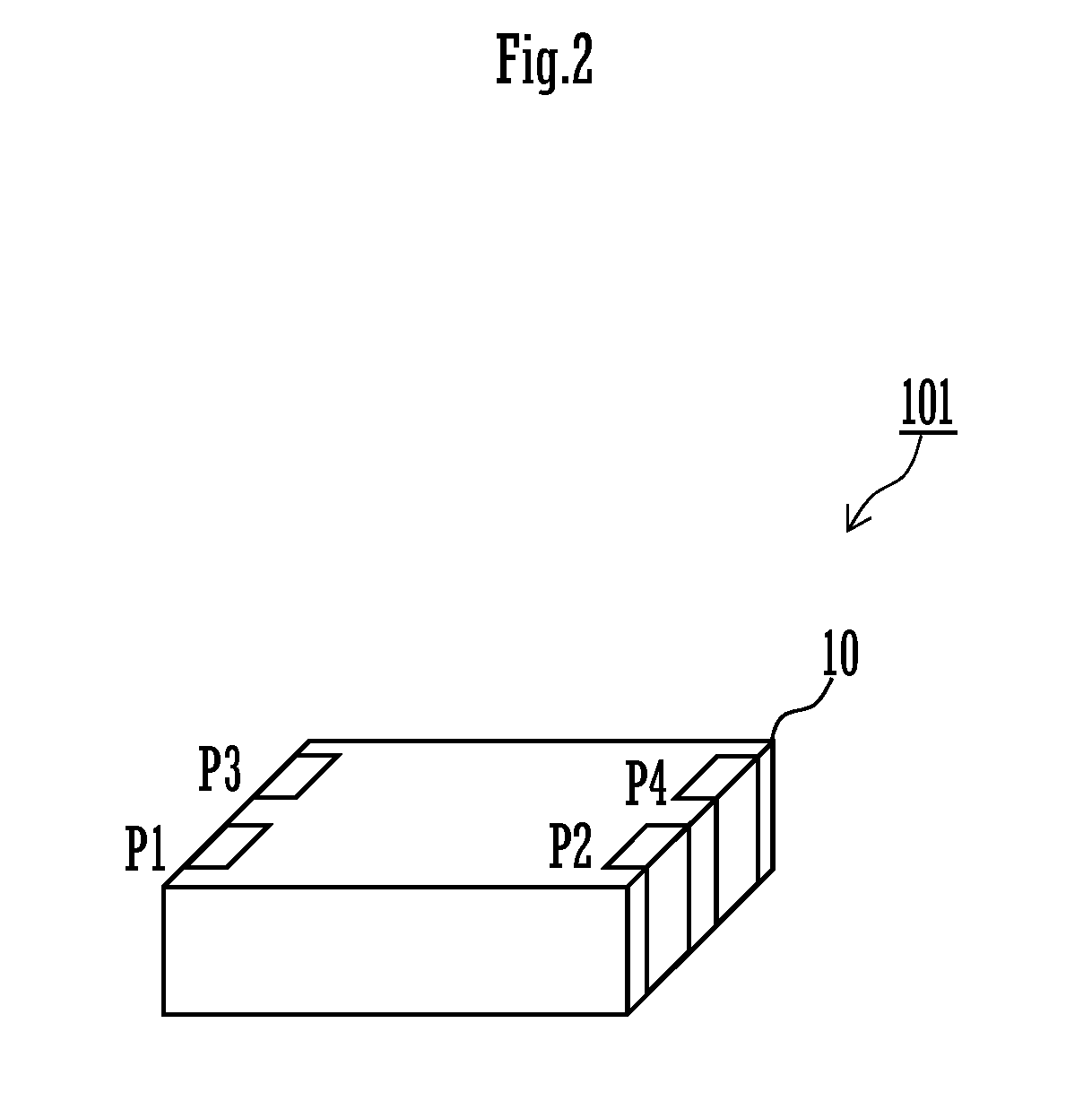
[0029]FIG. 1 is an exploded plan view showing conductor patterns and the like of the layers of a common-mode choke coil according to a first preferred embodiment of the present invention. FIG. 2 is an external perspective view of the common-mode choke coil 101 according to the first preferred embodiment.

[0030]The common-mode choke coil 101 is a laminated common-mode choke coil including a lamination element 10, which is made up of a plurality of base layers including base layers denoted by (1) to (9) in FIG. 1 being laminated on each other, and a primary coil and a secondary coil which are provided in the lamination element and coupled to each other.

[0031]In FIG. 1, the layer (1) is the lowermost layer, and the layer (9) is the uppermost layer. As shown in FIG. 1, electrodes of input / output terminals P1 to P4 are provided on the base layer (1). First annular conductors are provided on the base layers (2), (4), (6), and (8). Second annular conductors are provided on the base layers (...

second preferred embodiment

[0056]FIG. 6 is a schematic cross-sectional view of a common-mode choke coil 102 according to a second preferred embodiment of the present invention. In this common-mode choke coil 102, the outermost layers are each defined by a magnetic layer 10m, and the first annular conductors L1a to L1h and the second annular conductors L2a to L2h are provided on a non-magnetic layer (a low-permeability layer, a dielectric layer) 10n. The non-magnetic layer 10n and the annular conductors preferably have the structure identical to that of the common-mode choke coil 101 according to the first preferred embodiment. The relative permeability μr of the non-magnetic layer 10n is 1, and the relative permeability μr of the magnetic layer 10m is about 200 to 500, for example.

[0057]Since the magnetic field shown in FIG. 5A is generated by common-mode current, magnetic flux passes through the magnetic layers 10m. Accordingly, the inductance value becomes further greater effectively to common-mode noise. F...

third preferred embodiment

[0058]FIG. 7 is an exploded plan view showing conductor patterns and the like of the layers of a common-mode choke coil according to a third preferred embodiment of the present invention. FIG. 8 is an external perspective view of the common-mode choke coil 103 according to the third preferred embodiment. FIG. 9A is a cross-sectional view of the common-mode choke coil 103. FIG. 9B is a cross-sectional view of an ESD protection element portion.

[0059]The common-mode choke coil 103 is a laminated common-mode choke coil having a lamination element 10, which includes a plurality of base layers including base layers denoted by (1) to (24) in FIG. 7 being laminated on each other, and a primary coil and a secondary coil which are provided on the lamination element and coupled to each other.

[0060]FIG. 7 shows the layers (1) to (24) of the lamination element, and the shape of conductor patterns and the like provided on the layers. The layer (1) is the lowermost layer, and the layer (24) is the...


PUM

PropertyMeasurementUnit
thicknessaaaaaaaaaa
thicknessaaaaaaaaaa
thicknessaaaaaaaaaa

Abstract

In a common-mode choke coil, first annular conductors are helically defined from the lower layer to the upper layer, and first annular conductors are helically defined from the upper layer to the lower layer. Further, second annular conductors are helically defined from the lower layer to the upper layer, and second annular conductors are helically defined from the upper layer to the lower layer. The first annular conductors and the second annular conductors are disposed alternately in a lamination direction. The first annular conductors and the second annular conductors are disposed such that substantial portions of the annular conductors adjacent to each other in the layer direction do not overlap in a planar view. This structure achieves a compact common-mode choke coil with which the loss of normal-mode signals is small, and which is highly capable of removing common-mode noise.

Description

BACKGROUND OF THE INVENTION[0001]1. Field of the Invention[0002]The present invention relates to a laminated common-mode choke coil applied to a transmission line of high-frequency signals.[0003]2. Description of the Related Art[0004]For example, with a high-speed interface such as the USB (Universal Serial Bus) and the HDMI (High Definition Multimedia Interface), “the differential transmission scheme” in which signals that are 180° out of phase with each other are respectively transmitted through a pair of signal lines (=balanced line) is used. Since radiated noise and external noise are canceled out at the balanced line with the differential transmission scheme, such kinds of noises are less influential. However, practically speaking, particularly with a signal line for a high-speed interface, common-mode noise current attributed to asymmetry of the signal line occurs. Accordingly, in order to suppress the common-mode noise, a common-mode choke coil is used for a high-speed interf...

Claims


Application Information

Patent Timeline
Patent Type & Authority Applications(United States)
IPC IPC(8): H01F17/00H02H9/04
CPCH03H7/427H01F17/00H01F19/00H02H9/04H03H2001/0085H01F17/0033H03H7/0107H01F17/0013H01F27/292H01F2017/0093H01F27/2804H01F27/343H01F2027/2809H01F2027/348
Inventor KATO, NOBORUNOMA, TAKASHIAKIYAMA, HISASHI
Owner MURATA MFG CO LTD
Why Eureka
Try Eureka