Pure metal and ceramic nanofibers

a technology of ceramic nanofibers and metals, applied in the direction of zirconium oxides, copper oxides/halides, conductive materials, etc., can solve the problems of poor coherence, low performance, unsuitability for many applications, etc., and achieve low cost, flexible control, and low voids and/or defects.

Inactive Publication Date: 2014-11-13
CORNELL UNIVERSITY
View PDF7 Cites 44 Cited by
  • Summary
  • Abstract
  • Description
  • Claims
  • Application Information

AI Technical Summary

Benefits of technology

[0003]Provided herein are nanofibers and processes for producing nanofibers. In some instances, the nanofibers are metal, metal oxide, and/or ceramic nanofibers. In some embodiments, the nanofibers are high quality nanofibers, high performance nanofibers, highly coherent nanofibers, highly continuous nanofibers, or the like. In some embodiments, the nanofibers are coherent, are long, have few voids and/or defects, and/or have other advantageous characteristics such as flexibl...

Problems solved by technology

However, the nanofibers produced by the sol-gel method have many disadvantages, such...

Method used


Image

  • Pure metal and ceramic nanofibers
  • Pure metal and ceramic nanofibers
  • Pure metal and ceramic nanofibers

Examples


example 1

Preparing a Fluid Stock of Nickel Acetate and PVA

[0375]Two (2) grams of nickel acetate, the metal precursor, was dissolved in 20 ml of 1 molar acetic acid solution. The solution was stirred for 2 hours to create a solution of nickel acetate. The solution was homogenous.

[0376]In a second solution, 1 gram of 99.7% hydrolyzed polyvinyl alcohol (PVA) with an average molecular weight of 79 kDa and polydispersity index of 1.5 was dissolved in 10 ml of de-ionized water. The polymer solution was heated to a temperature of 95° C. and stirred for 2 hours to create a homogenous solution.

[0377]The nickel acetate solution was then combined with the PVA solution to create a fluid stock. In order to distribute the precursor substantially evenly in the fluid stock, the precursor solution was added gradually to the polymer solution while being continuously vigorously stirred for 2 hours. The mass ratio of precursor to polymer for the fluid feed (based on initial nickel acetate mass) was 2:1.

example 2

Characterization of a Fluid Stock of Nickel Acetate and PVA

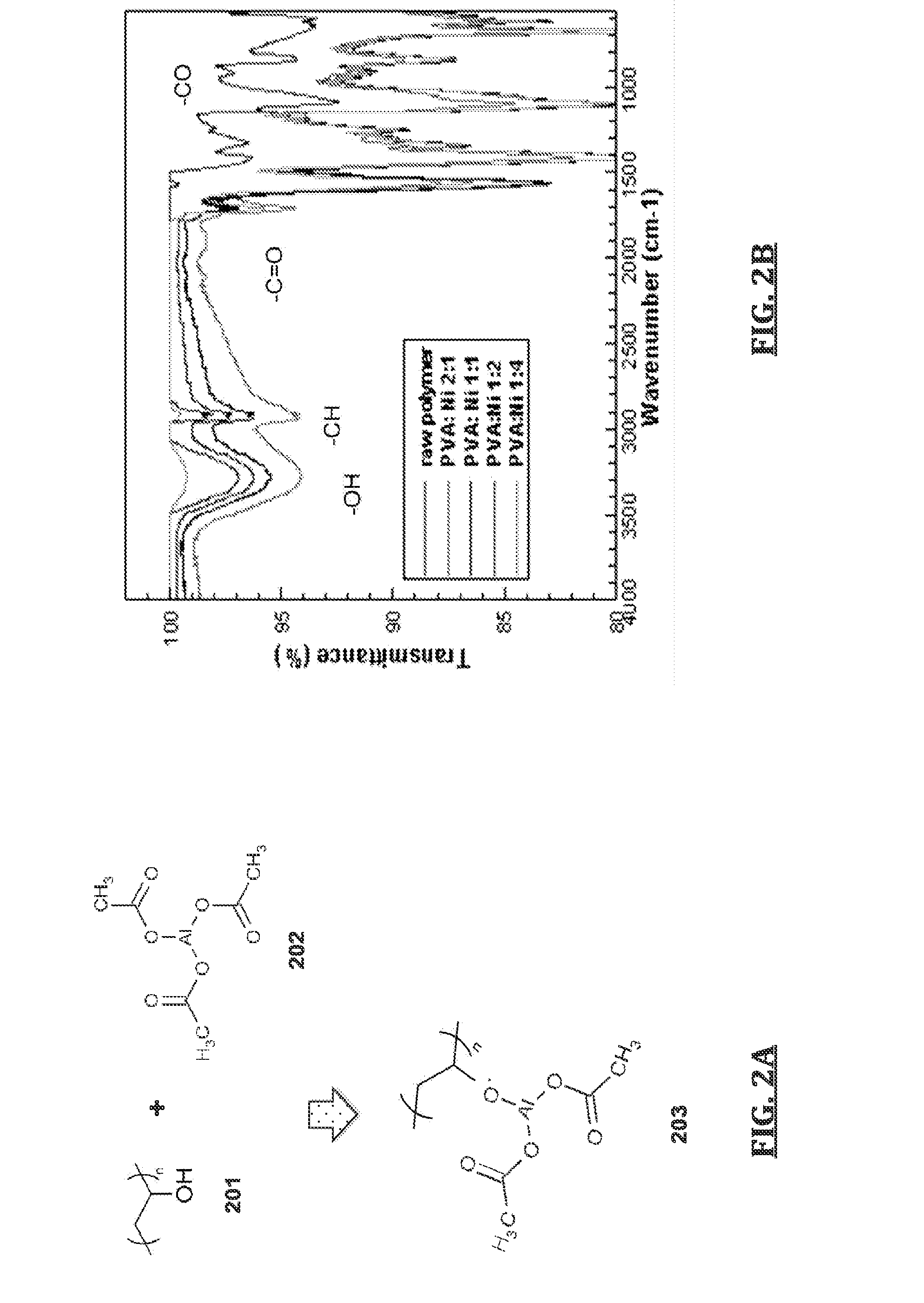
[0378]The chemical interaction between the ligand of the metal precursor and the functional group in the polymer backbone resulted in extremely high loading of metal precursors without losing the spinnability. The interaction was demonstrated in the FT-IR study for nanofibers with various ratios of PVA to Ni precursor. As demonstrated in FIG. 2, the drastic reduction of —OH bond and substantial increase in —CO bond were observed at high loading of Ni precursor (Ni:PVA=4:1).

example 3

Electrospinning a Fluid Stock of Nickel Acetate and PVA

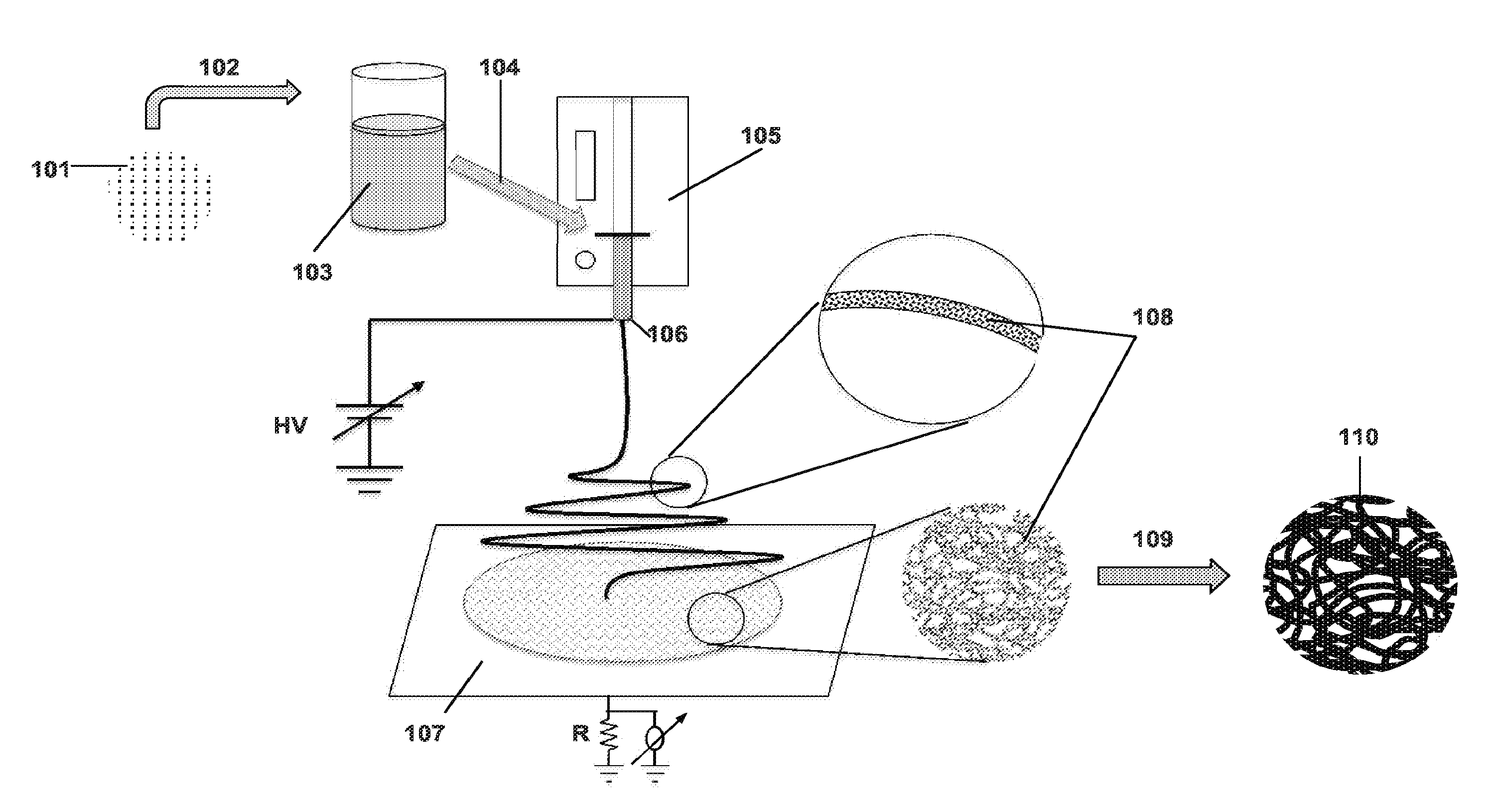
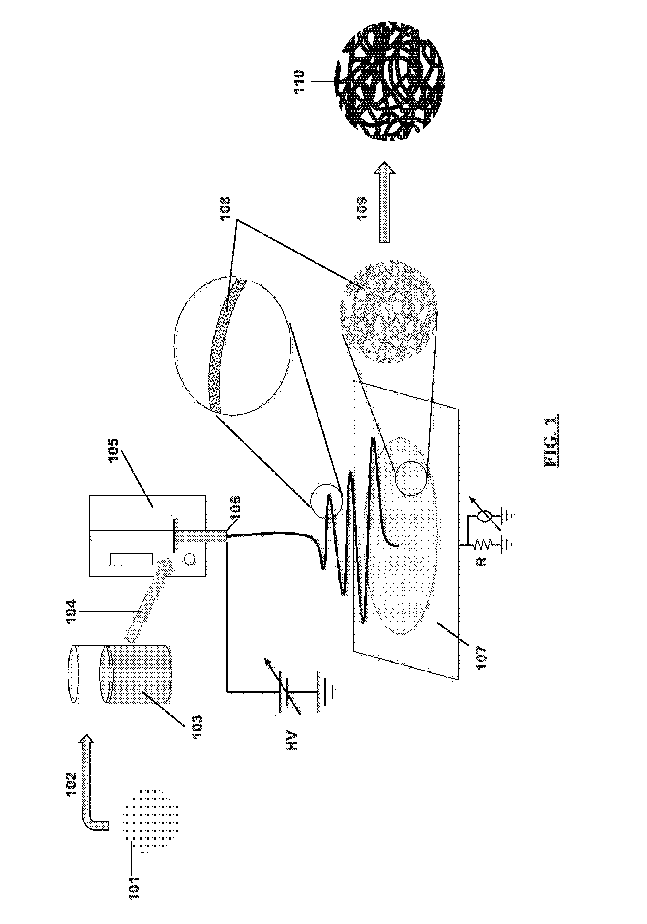
[0379]The fluid stock of Example 1 was electrospun by a gas-assisted technique. The overall process and apparatus is depicted in FIG. 1. The fluid stock was loaded into a syringe pump connected to a spinneret with an inner nozzle diameter (fluid stock) of 4.13×10⁻⁴ m and an outer (air) diameter of 1.194×10⁻³ m. The distance between the nozzle and the collection plate was kept at about 15 cm and the fluid stock was spun at a rate of 0.1 ml / min. A charge of +15 kV was maintained at the collector. The air velocity at the nozzle was 100 m / s. The temperature of the air and fluid stock at the nozzle was 300 K.


PUM

PropertyMeasurementUnit
Temperatureaaaaaaaaaa
Fractionaaaaaaaaaa
Molar densityaaaaaaaaaa

Abstract

Provided herein are nanofibers and processes of preparing nanofibers. In some instances, the nanofibers are metal and/or ceramic nanofibers. In some embodiments, the nanofibers are high quality, high performance nanofibers, highly coherent nanofibers, highly continuous nanofibers, or the like. In some embodiments, the nanofibers have increased coherence, increased length, few voids and/or defects, and/or other advantageous characteristics. In some instances, the nanofibers are produced by electrospinning a fluid stock having a high loading of nanofiber precursor in the fluid stock. In some instances, the fluid stock comprises well mixed and/or uniformly distributed precursor in the fluid stock. In some instances, the fluid stock is converted into a nanofiber comprising few voids, few defects, long or tunable length, and the like.

Description

CROSS-REFERENCE[0001]This application claims the benefit of U.S. Provisional Application Nos. 61 / 528,895, filed Aug. 30, 2011, and 61 / 636,095, filed Apr. 20, 2012, both of which are incorporated herein by reference in their entireties.BACKGROUND OF THE INVENTION[0002]Ceramic and metallic nanofibers have potential for applications in a wide variety of fields, including high performance filtration, chemical sensing, biomedical engineering and renewable energy. Previous methods for producing ceramic or metallic nanofibers include the electrospinning of sol-gel precursors with or without a polymer binder. However, the nanofibers produced by the sol-gel method have many disadvantages, such as low performance and poor coherence, which makes them unsuitable for many applications.SUMMARY OF THE INVENTION[0003]Provided herein are nanofibers and processes for producing nanofibers. In some instances, the nanofibers are metal, metal oxide, and / or ceramic nanofibers. In some embodiments, the nan...

Claims


Application Information

Patent Timeline
IPC IPC(8): D01D5/00B22F1/00H01B1/02D01F1/10H01B1/08
CPCD01D5/0015D01F1/10H01B1/08H01B1/026H01B1/02B22F1/0044D04H1/4234D04H1/728D01D5/0007C04B35/62227B22F9/30B82Y30/00C04B35/62231C04B35/62236C04B35/6224C04B35/6225C04B35/62254C04B35/62259C04B2235/40C04B2235/441C04B2235/443C04B2235/444C04B2235/449C04B2235/526C04B2235/5264C04B2235/5296D01F9/08A61K31/202A61K31/232B22F1/0547B22F1/07D01D5/003D01F9/10
Inventor JOO, YONG LAKHANSEN, NATHANIEL S.CHO, DAEHWAN
Owner CORNELL UNIVERSITY
Why Eureka
Try Eureka