Method and system for managing heat disipation in doped fiber

a technology of heat dissipation and fiber, applied in the direction of electrical equipment, active medium shape and construction, laser details, etc., can solve the problems of significant heating along the active fiber, low laser process conversion efficiency, and no longer guided light at high angles, so as to reduce the overall temperature, facilitate heat dissipation, and eliminate the effect of fiber crossover

Inactive Publication Date: 2014-12-11
PRIMA ELECTRO NORTH AMERICA
View PDF8 Cites 14 Cited by
  • Summary
  • Abstract
  • Description
  • Claims
  • Application Information

AI Technical Summary

Benefits of technology

[0014]In still a further embodiment a winding plate is employed to provide predefined spacing between packaged arrays to reduce the overall temperature and facilitate hea...

Problems solved by technology

As a result, this light energy within the fiber can result in significant heating along the active fiber.
Heating can result because the laser process conversion efficiency is always less than 100% with most of the unconverted energy released as thermal energy.
Further, the glass type(s) used in the active fiber typically have transmission loss (absorption and re-emission) that also converts energy having wavelengths of greater than 2000 nm into heat.
Still further, light that is scattered in the fiber and light at high angle...

Method used


Image

  • Method and system for managing heat disipation in doped fiber
  • Method and system for managing heat disipation in doped fiber
  • Method and system for managing heat disipation in doped fiber

Examples


Embodiment Construction

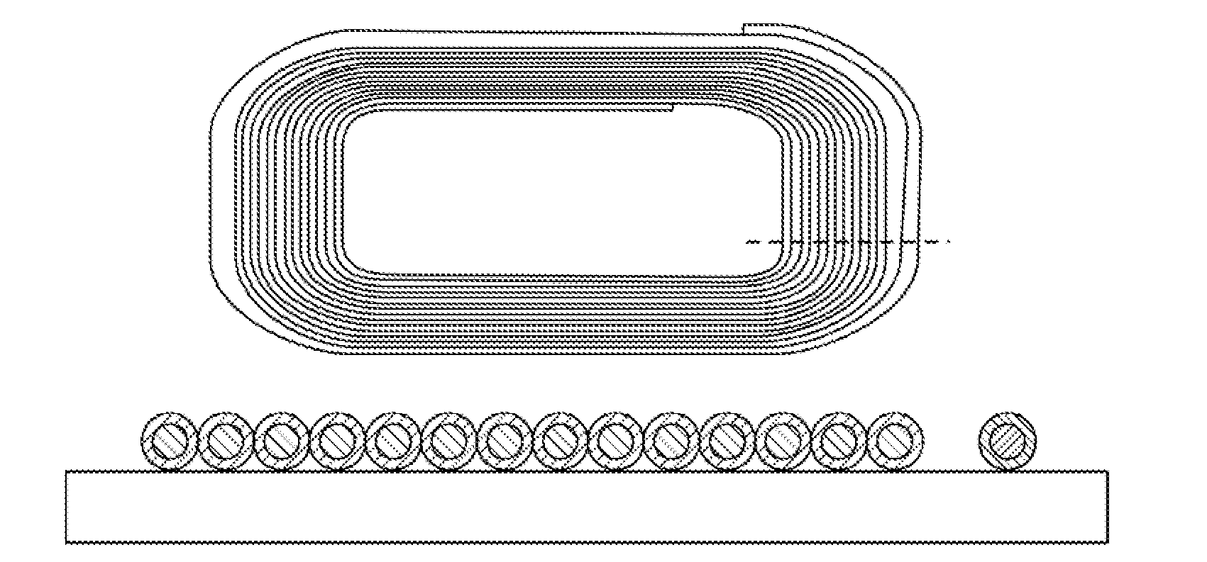
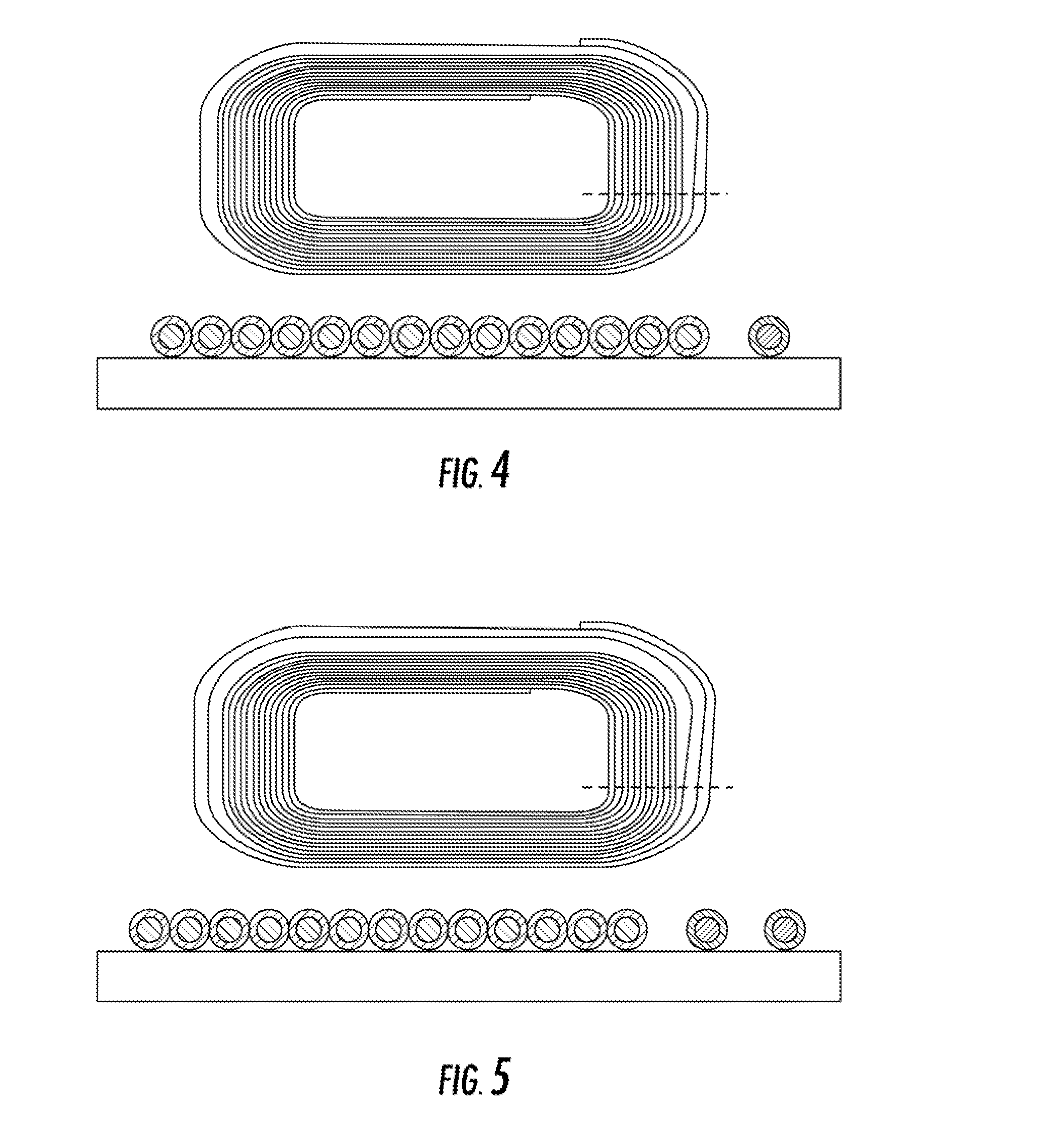
[0028]Now referring to the drawings, the system for managing the heat dissipation and local thermal increases of an active, doped optical fiber that is being pumped by light source is shown and generally illustrated. The present invention may be implemented using a CW, a pulsed fiber light source, fiber laser or a fiber amplifier for the purpose of removing or redistributing heat from the doped / active optical fiber allowing it to operate at a lower temperature.

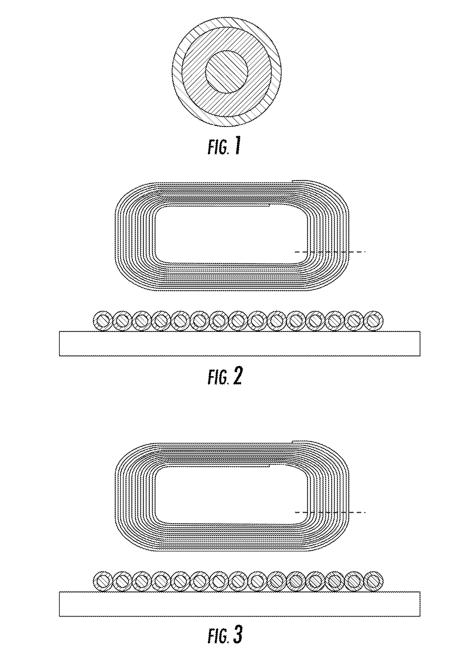
[0029]In a fiber laser, the optical fiber, as shown in FIG. 1, typically consists of three regions, a central core glass, a surround cladding glass and a 2nd cladding or “coating” (typically polymer or low index glass). The gain medium of fiber lasers is a length of an optical fiber, the core of which is doped with an active lasing material, typically ions of a rare earth element, such as Ytterbium, Erbium, Thulium, Praseodymium etc. The active elements are introduced during the optical fiber manufacturing process and are loca...


PUM


Abstract

An improved fiber array arrangement is provided that incorporates spacing and/or spacers between active fibers in a winding to reduce maximum active fiber temperature, with the spacing/spacer material distributed to minimize heating at locations of high pump power. Spacer material such as “dark” fibers and/or metal wires of similar diameter as the active fiber may be employed to aid winding/bundling of active fibers. Further, the use of channels, grooves, wall material and combinations thereof aid structural support/guidance for the winding/bundling of active fibers while providing predefined spacing and heat conductivity that reduces the maximum thermal temperature of the active fiber below design thresholds.

Description

BACKGROUND OF THE INVENTION[0001]The present invention relates generally to the management of heat dissipation, overall heat distribution and local thermal increases of active fibers being pumped by a light source. More specifically, the present invention relates to methods and systems for managing the heat dissipation from pumped fiber lasers and or fiber amplifiers in an arrangement that allows higher pumping powers while reducing cladding failure.[0002]Advances in laser technology have allowed for the development of increasingly high powered systems. Such high powered systems include free space lasers, as well as lasers confined to waveguides, such as fiber lasers and fiber laser amplifiers. Fiber lasers have significant advantages over traditional lasers, including stability of alignment, scalability and high optical power of a nearly diffraction limited output beam.[0003]In a fiber laser, the optical fiber typically consist of three regions, a central core glass, a surround cla...

Claims


Application Information

Patent Timeline
IPC IPC(8): H01S3/067
CPCH01S3/06733H01S3/06704H01S3/0405
Inventor SCHWARZENBACH, PIETERSILVA SA, MATTHEW J.REEVES-HALL, PETER
Owner PRIMA ELECTRO NORTH AMERICA
Why Eureka
Try Eureka