
Design of a conduit for peripheral nerve replacement

a peripheral nerve and conduit technology, applied in the direction of non-metal conductors, prostheses, conductors, etc., can solve the problems of limiting the repair of peripheral nerves to a maximum gap of 3 cm, unable to treat over 87 patients, and ineffective attempts to exceed the 3 cm boundary

Active Publication Date: 2015-01-29
WAKE FOREST UNIV HEALTH SCI INC
View PDF9 Cites 17 Cited by
  • Summary
  • Abstract
  • Description
  • Claims
  • Application Information

AI Technical Summary

Benefits of technology

The present invention is about developing materials and devices for repairing transected peripheral nerves. The invention involves creating biphasic materials that can promote neurite outgrowth and axonal repair following a peripheral nerve transection. The materials have high conductivity and can support differing electric field gradients. The invention also includes a telescoping segmented apparatus and a sheet or strip comprising the biphasic material. The technical effects of the invention include promoting nerve regeneration and improving the function of peripheral nerves.

Problems solved by technology

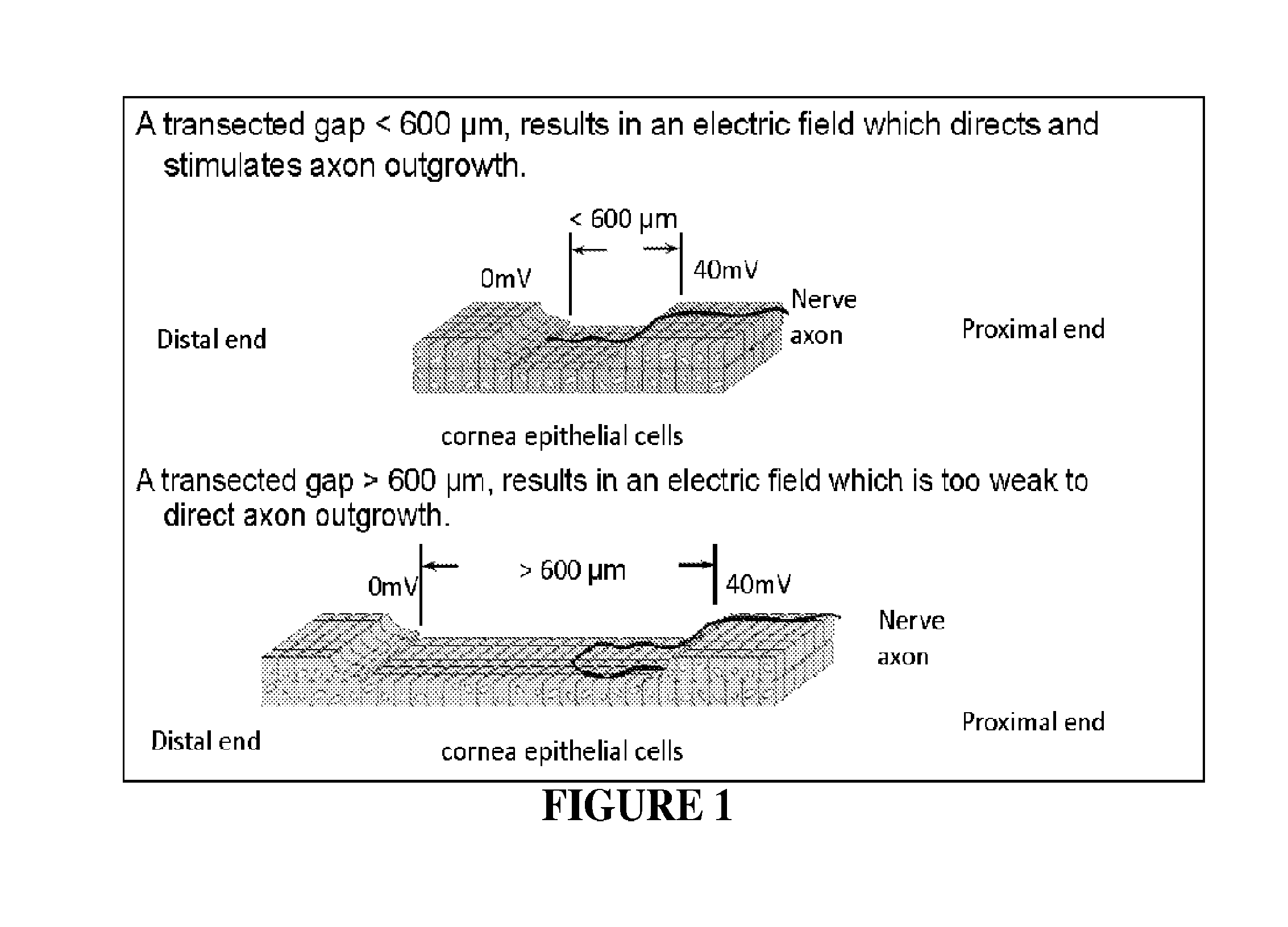
However, no treatment options are available for over 87% of patients having transacted nerve gaps greater than 3 cm because rapid scar formation overcomes slow nerve outgrowth.
Indeed, current surgical options limit repair of peripheral nerves to a maximum gap of 3 cm.
Attempts to surpass this 3 cm boundary have been ineffective.
Current surgical procedures for peripheral nerve damage are inadequate.
Autografts and allografts are currently used but the availability and section of grafts and immunosuppression to prevent graft rejection are problems associated with graft procedures.
Additionally, various types of conduits have been used for peripheral nerve replacement, but typically lack chemical, biological, and morphological guidelines provided by grafts.
Among the drawbacks associated with presently deployed grafts and conduits is the fact that the repair, as stated, is limited to gaps of up to 3 cm in length.
The length limitation is likely due to a lack of chemical and / or electrical stimuli.
Due to the present limitations in the art for treating and repairing peripheral nerve damage, new therapies, materials and devices are needed.

Method used


Image

  • Design of a conduit for peripheral nerve replacement
  • Design of a conduit for peripheral nerve replacement
  • Design of a conduit for peripheral nerve replacement

Examples


example 1

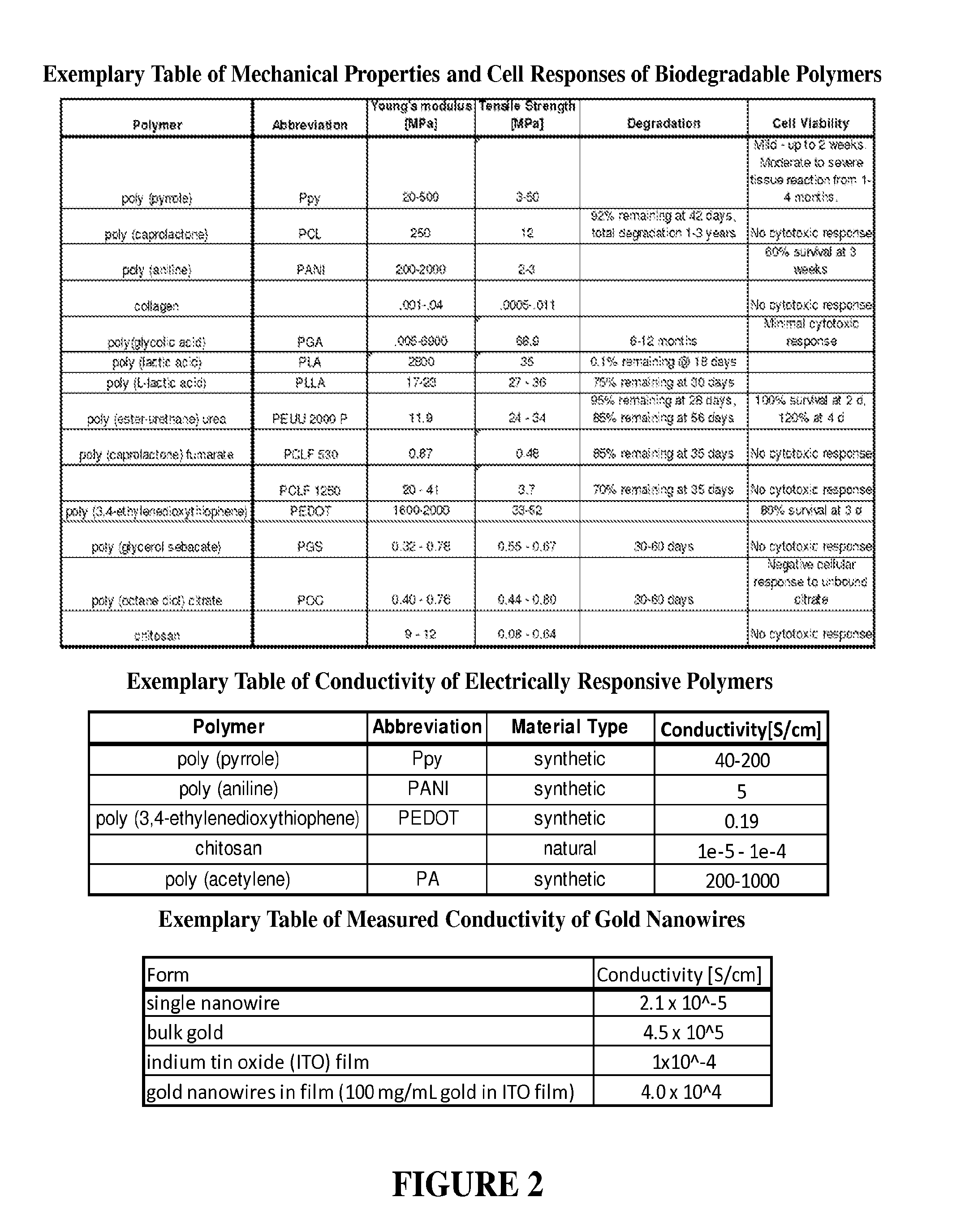
[0093]Conductive materials can be enhanced by low concentrations (0-5%) of metal nanowires to increase material conductivity. We have synthesized silver nanowires with resulting solutions comprised of short nanorods (aspect ratio (A.R.): 6.1±0.64 nm), medium length nanorods (A.R: 17.0±0.06), and long nanowires (AR: 34.02±3.01). We incorporated low concentrations (0-5% by weight) of the prepared silver nanorods into chitosan films (conductivity=10−6 S / cm) to evaluate changes in conductivity. We have achieved silver nanorods in the desired size range and successfully generated chitosan films doped with silver nanowires. (See FIGS. 6 and 7). Stable chitosan conductivity measures require input voltages in the range of 2 to 100 kV to achieve read voltages in the range of 2-100 V across the film. Distinction of conductivity for nanowire doping variation requires minimum input voltages of 10 kV. These input voltages are not reasonable options for human or animal modeling. These experiments...

example 2

[0094]A conduit of the present invention was prepared and tested utilizing PGSA. See FIG. 8.

[0095]Methods.

[0096]PGS was prepared by melting sebacic acid (Sigma 283258) in an oil bath at 180° C., under nitrogen. Glycerol (Fisher Scientific G33) preheated to 100° C. was added dropwise to sebacic acid (3:1 w / v sebacic acid: glycerol). The prepolymer was completed by applying 15 in Hg vacuum pressure while stirring 4 hours with the oil bath maintained at 150° C.

[0097]Synthesis of PGSA.

[0098]PGSA was prepared by melting PGS into an excess solution of dichloromethane (Fisher D37). PGS was acrylated to 25, 30, 35, and 40% of its hydroxyl groups using 25, 30, 35, or 45% molar amounts of acryloyl chloride (Sigma A24109). Hydrochloric acid was removed from equilibrium via vaporization with the dropwise addition of triethylamine (Sigma T0886) (1.2:1.0, triethylamine:acryolyl chloride). Dichloromethane was removed by rotovaporization. Triethylamine salts were precipitated from the solution usin...

example 3

Prospective Development and Evaluation of an Additional Segmented Conduction Conduit

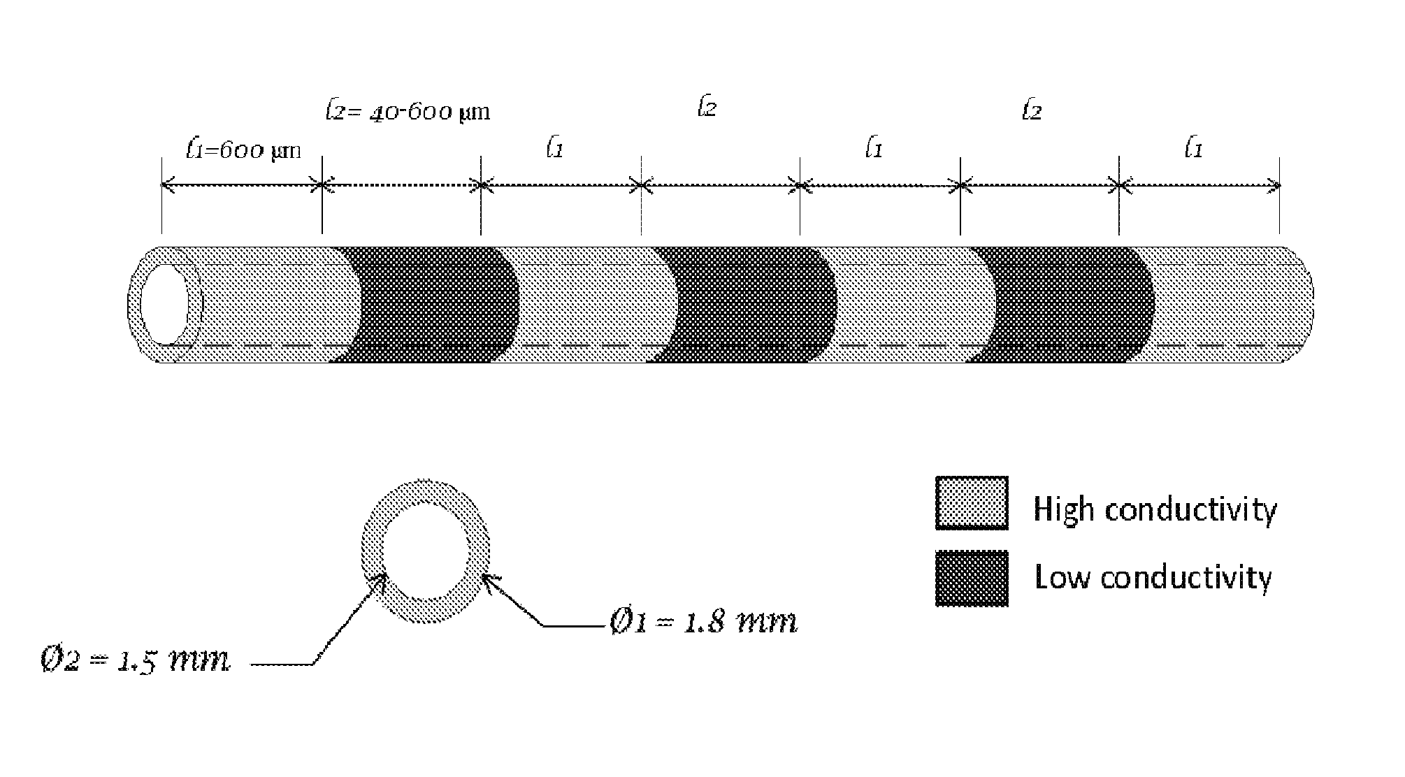
[0156]Results from one hour of AC electrical stimulation of nerves proximal to the site of injury demonstrate axon regeneration rate increase over three times compared to the untreated rate of regeneration. The observation in the axon extension process following electrical stimulation is a decreased delay time for axon elongation and increased axon sprouts. These repair actions over a limited time range motivate evaluation of extended stimulation. However, extended stimulation time yielded no improvement. Reflection on newt limb and bovine corneal studies implies that the limiting factor may be distance of effectiveness of single point electrical stimulation (measured as 600 μm), rather than time length of stimulation. This observation provides further biological support for incremental electrical field stimulation. To answer the question: “Is the critical gap size for nerve repair limited by the lac...


PUM

PropertyMeasurementUnit
Lengthaaaaaaaaaa
Lengthaaaaaaaaaa
Timeaaaaaaaaaa

Abstract

A biphasic material and devices comprising the same are provided for the development of conductive conduits that may be used for the treatment of peripheral nerve injury. These devices or conduits are designed such that repeated electric field gradients can be initiated to promote neurite and axonal outgrowth. Conducting conduits using doped synthetic and / or natural polymers create specifically patterned high and low conducting segmented materials, which are mechanically used to produce the electrical properties needed for nerve conduits. These electrical properties stimulate neurite outgrowth and axonal repair following a peripheral nerve transection.

Description

RELATED APPLICATIONS[0001]This application claims the benefit of U.S. Provisional Application No. 61 / 623,528, filed Apr. 12, 2012, the entirety of which is incorporated by reference herein.FIELD OF THE INVENTION[0002]The present invention relates generally to biphasic materials and devices comprising the same and more particularly but not exclusively to biphasic polymeric materials including conductive polymers and conduits composed of the same for the treatment of peripheral nerves.BACKGROUND OF THE INVENTION[0003]Peripheral nerve impairment is caused by diseases, therapies, and injuries resulting in over 50,000 surgical procedures in the U.S. each year. Peripheral nerve repair is presently possible for transected nerve gaps of up to 3 cm. However, no treatment options are available for over 87% of patients having transacted nerve gaps greater than 3 cm because rapid scar formation overcomes slow nerve outgrowth. Indeed, current surgical options limit repair of peripheral nerves to...

Claims


Application Information

Patent Timeline
IPC IPC(8): A61B17/11A61L27/26H01B1/12C08G63/12C08G63/47A61F2/00A61L27/58
CPCA61B17/1128A61F2/0077A61L27/26A61L27/58C08G63/12A61L2430/32H01B1/125A61B2017/00004A61B2017/00831A61B2017/00991A61B2017/1132C08G63/47A61L27/18A61L27/446A61L27/50A61L2400/12C08L67/00
Inventor WAGNER, WILLIAM D.LEVI-POLYACHENKO, NICOLEROSENBALM, TABITHAARGENTA, LOUIS C.MORYKWAS, MICHAEL J.
Owner WAKE FOREST UNIV HEALTH SCI INC
Learn More