

Organic electroluminescent element
a technology of electroluminescent elements and organic materials, which is applied in the direction of luminescent compositions, energy-saving lighting, sustainable buildings, etc., can solve the problems of insufficient service life of panels, insufficient emission lifetime, and insufficient color purity in view of compatibility with wet coating processes, so as to achieve high color rendering properties, stable chromaticity, and high luminous efficiency
- Summary
- Abstract
- Description
- Claims
- Application Information
AI Technical Summary
Benefits of technology
Problems solved by technology
Method used
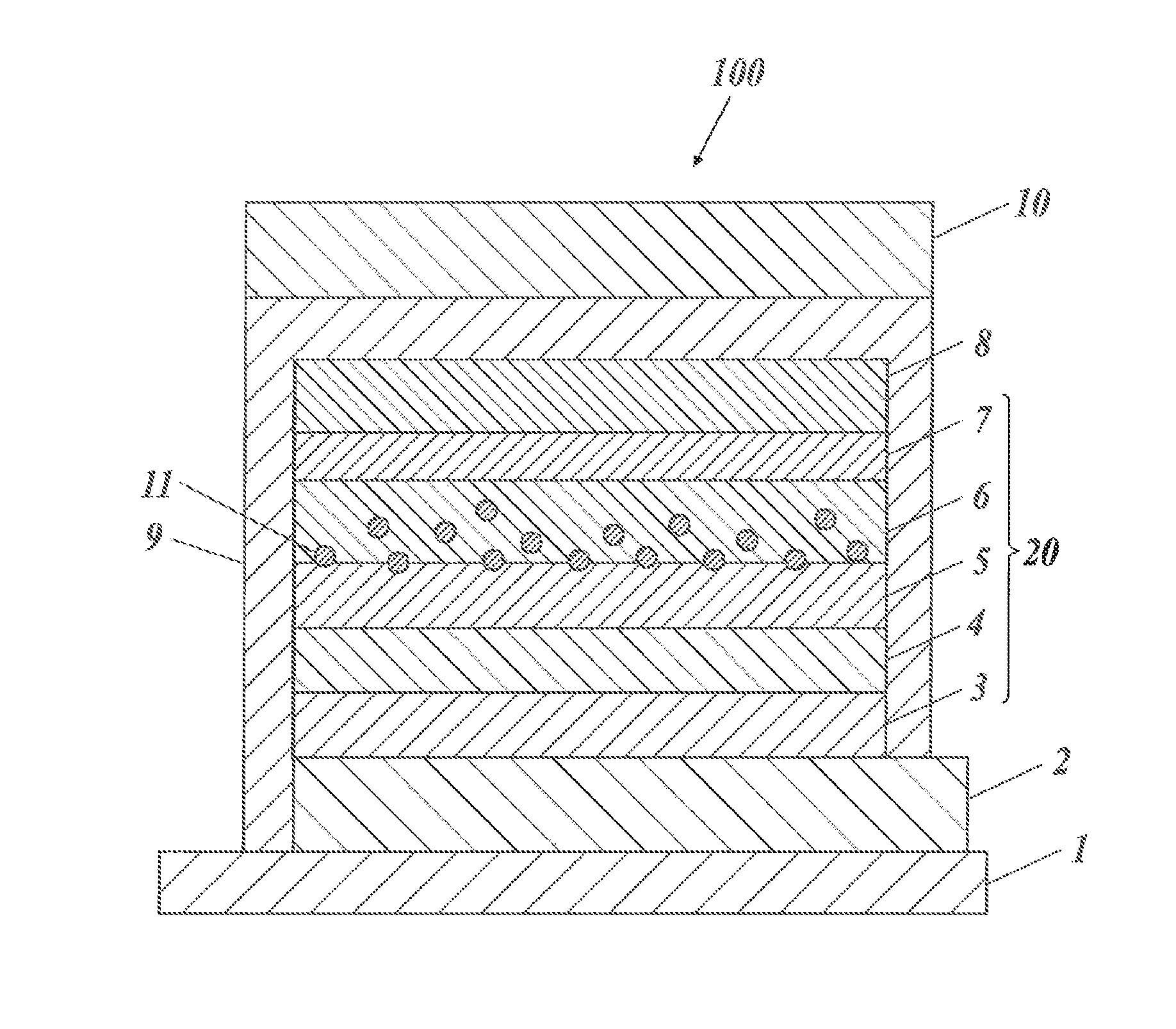
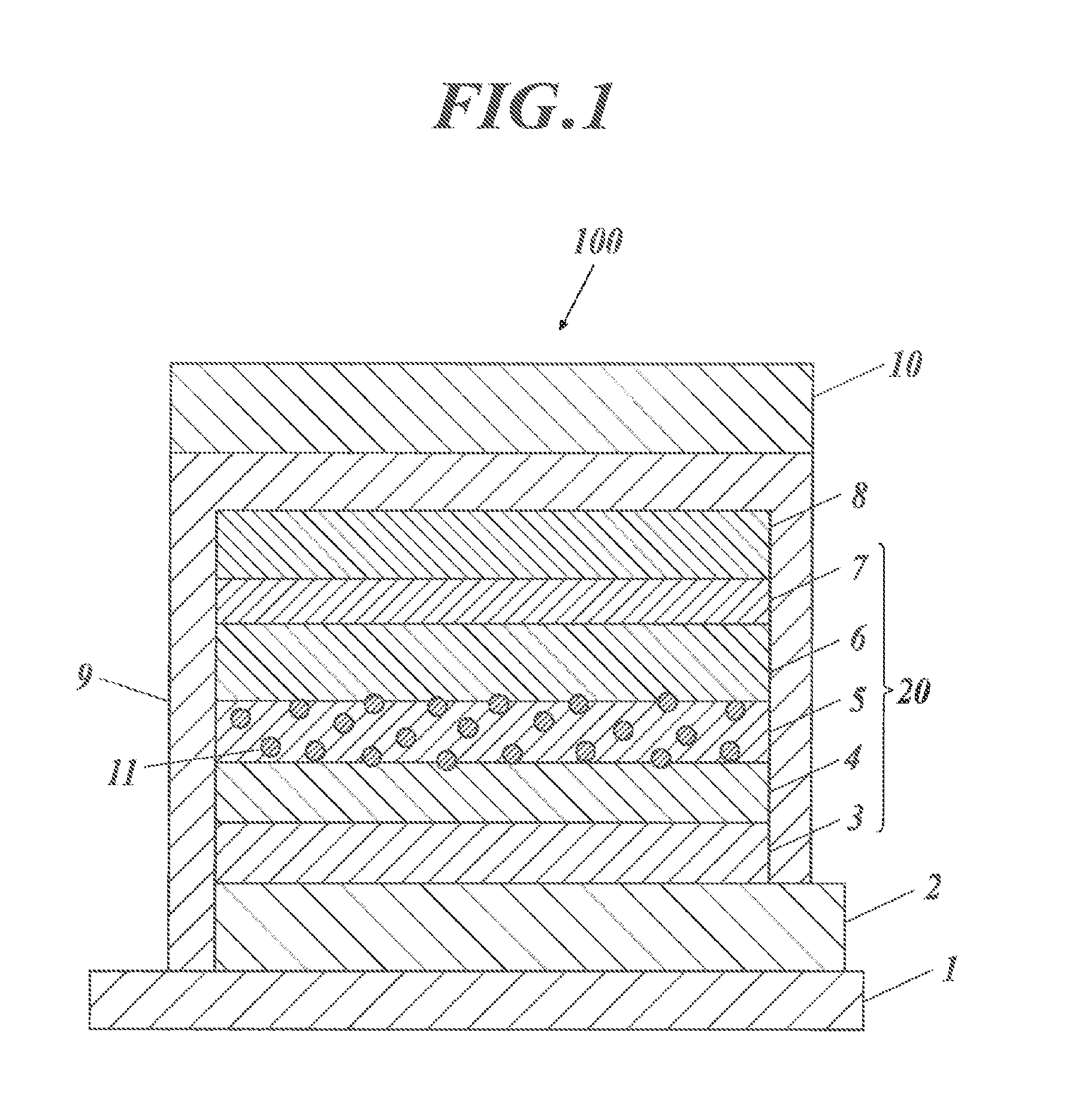
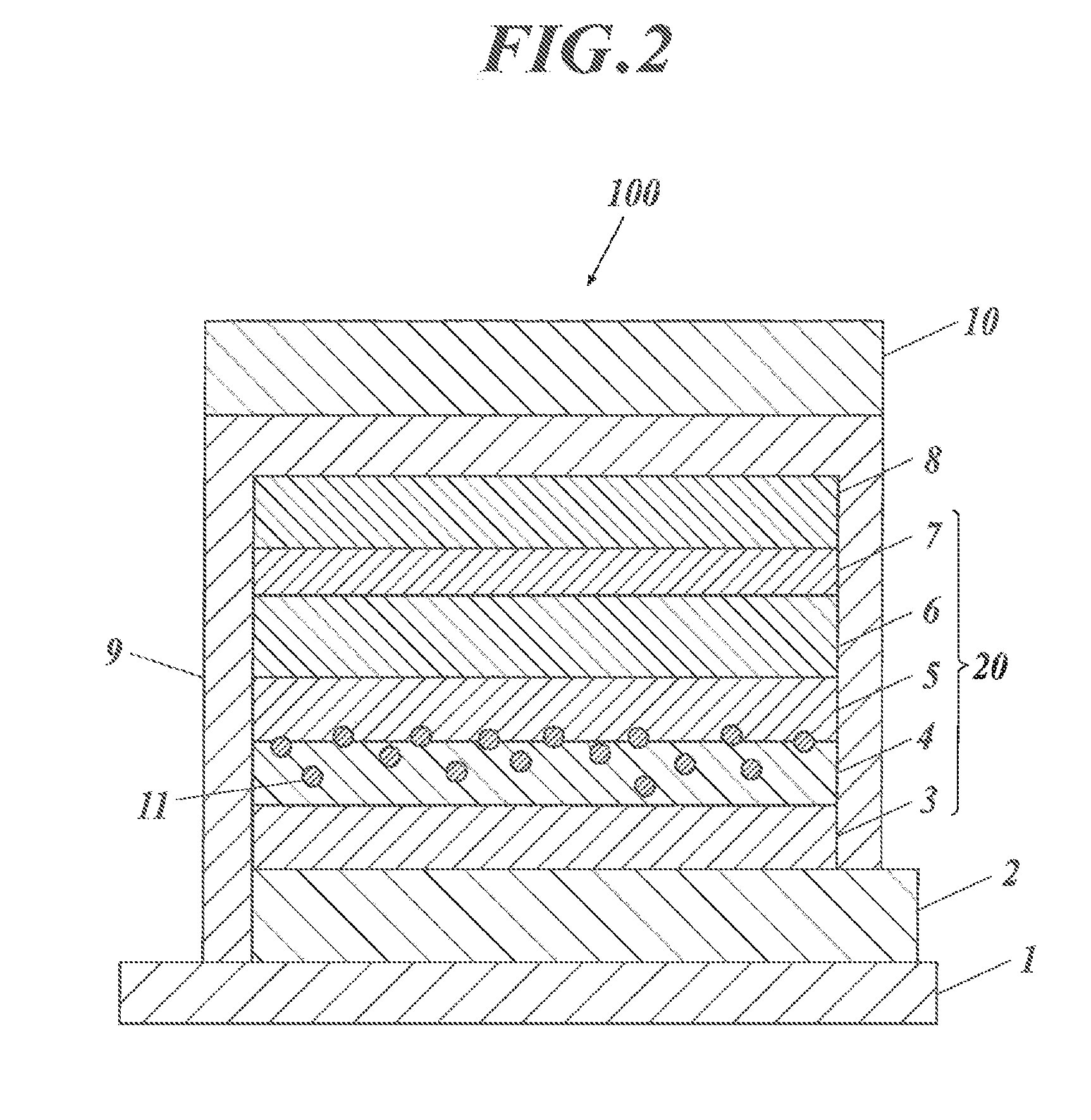
Image

Examples
example 1
Preparation of Organic EL Element
[0448]Blue luminescent organic EL elements 11 to 16 were prepared in accordance with the procedure described below.
[Preparation of Inventive Organic EL Element 11]
[0449](1.1) Preparation of Flexible Gas-Barrier Film
[0450]On an entire face (for formation of a first electrode) of a flexible poly(ethylene naphthalate) film (hereinafter referred to as PEN film) available from Teijin DuPont Films Japan Limited, an inorganic gas-barrier SiOx film was continuously formed into a thickness of 500 nm with an atmospheric plasma discharge system described in Japanese Unexamined Patent Application Publication No. 2004-68143. The resulting flexible gas-barrier film had an oxygen permeability of 0.001 ml / (m2·day·atm) or less and a moisture permeability of 0.001 g / (m2·day·atm) or less.
[0451](1.2) Formation of First Electrode Layer
[0452]Indium tin oxide (ITO) with a thickness of 120 nm was deposited by sputtering on the flexible gas-barrier film and was etched by pho...
example 2
Preparation of Organic EL Element
[0497]Blue luminescent organic EL elements 21 to 26 were prepared in accordance with the following procedure.
[Preparation of Inventive Organic EL Element 21]
[0498](1.1) Preparation of Flexible Gas-Barrier Film
[0499]On an entire face (for formation of a first electrode) of a flexible poly(ethylene naphthalate) film available from Teijin DuPont Films Japan Limited, an inorganic gas-barrier SiOx film was continuously formed into a thickness of 500 nm with an atmospheric plasma discharge system described in Japanese Unexamined Patent Application Publication No. 2004-68143. The resulting flexible gas-barrier film had an oxygen permeability of 0.001 ml / (m2·day·atm) or less and a moisture permeability of 0.001 g / (m2·day·atm) or less.
[0500](1.2) Formation of First Electrode Layer
[0501]Indium tin oxide (ITO) with a thickness of 120 nm was deposited by sputtering on the flexible gas-barrier film and was etched by photolithography to form a pattern of a first e...
example 3
Preparation of Organic EL Element
[0536]Blue luminescent organic EL elements 31 to 39 were prepared in accordance with the following procedure.
[Preparation of Comparative Organic EL Element 31: Comparison Example]
[0537](1) Formation of First Electrode Layer
[0538]Indium tin oxide (ITO) with a thickness of 100 nm was formed on a glass substrate with dimensions of 100 mm by 100 mm by 1.1 mm (NA 45 made by NH Technoglass Corporation) and was patterned into an anode. The transparent substrate provided with the transparent ITO electrode was ultrasonically cleaned in isopropyl alcohol, was dried in a dry nitrogen stream, and then was cleaned in a UV ozone environment for five minutes.
[0539](2) Formation of Hole Injection Layer
[0540]A solution of 70% poly(3,4-ethylene dioxythiophene)-polyethylenesulfonate (PEDOT / PSS), CLEVIO P VP Al 4083 available from H. C. Starck) in pure water was applied by spin coating on the transparent substrate provided with the ITO transparent electrode at 3000 rpm ...
PUM
| Property | Measurement | Unit |
|---|---|---|
| band gap | aaaaa | aaaaa |
| particle size | aaaaa | aaaaa |
| thickness | aaaaa | aaaaa |
Abstract
Description
Claims
Application Information