

Method and apparatus for the isolation of motile sperm
- Summary
- Abstract
- Description
- Claims
- Application Information
AI Technical Summary
Benefits of technology
Problems solved by technology
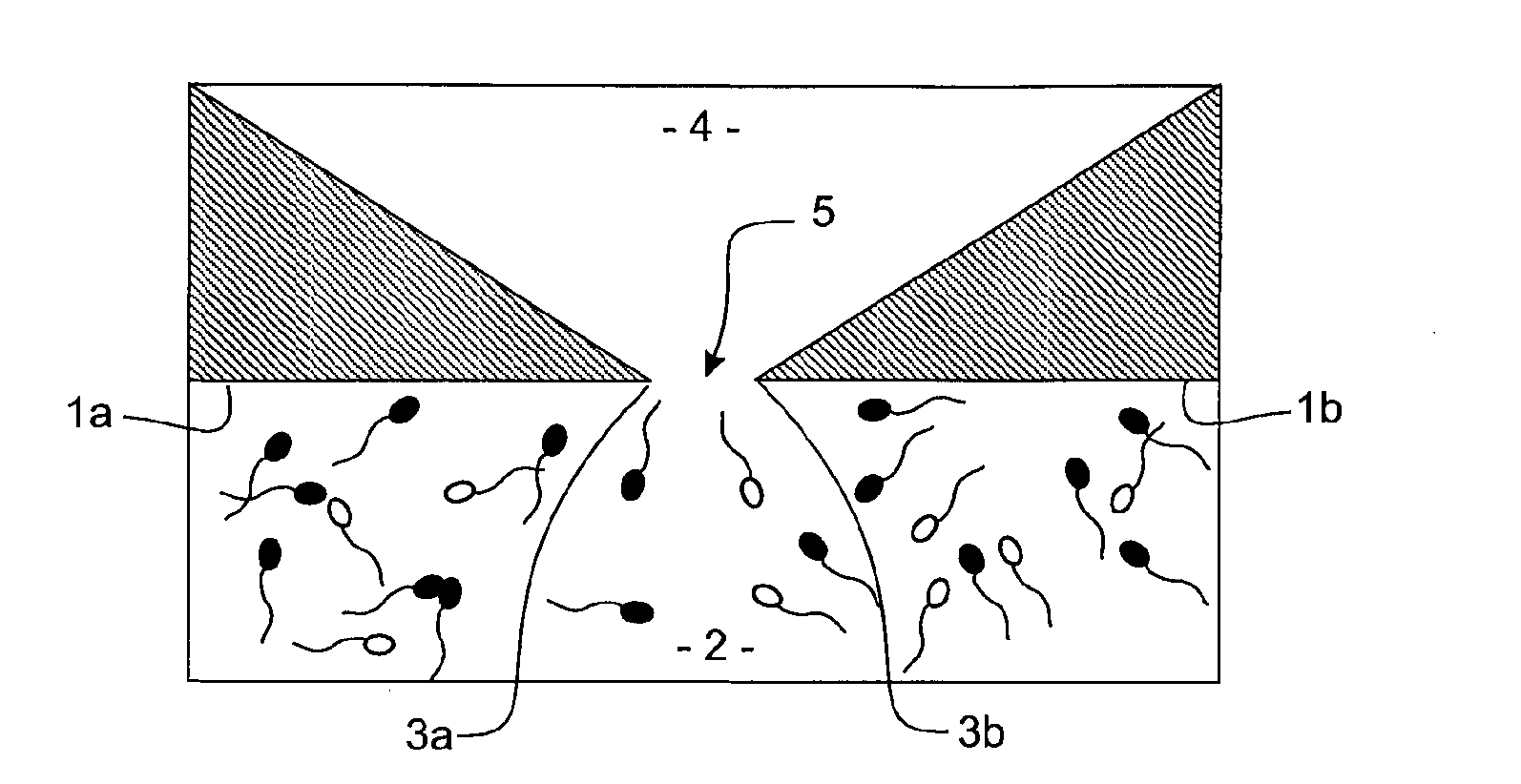
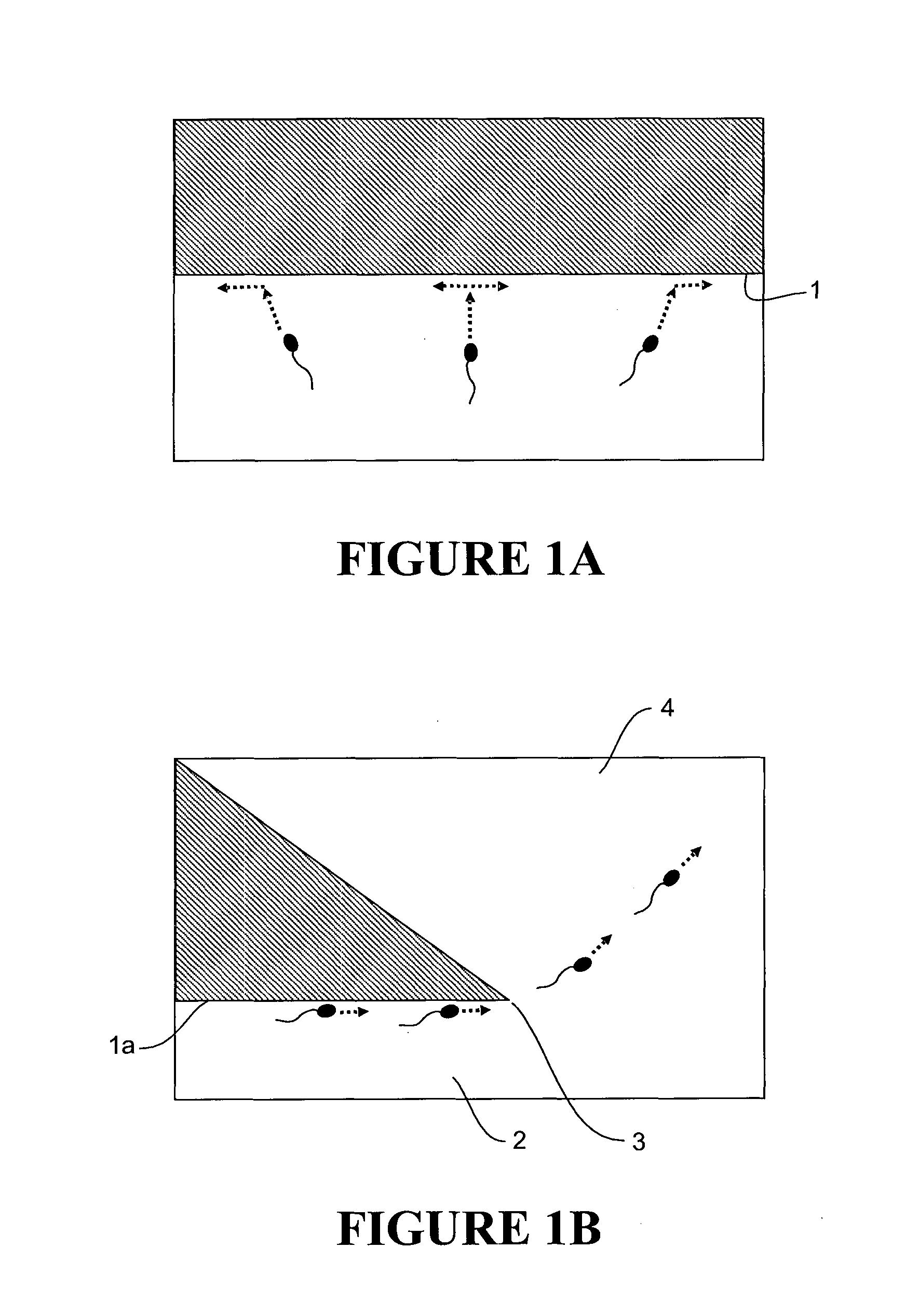
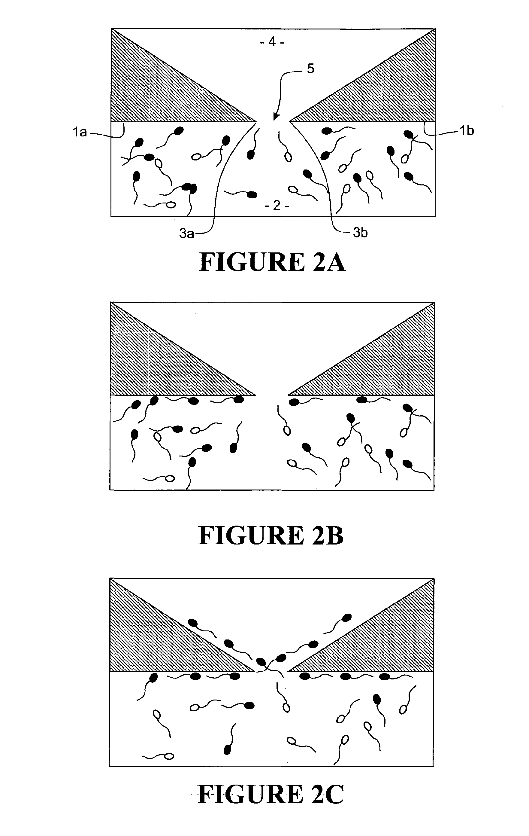
Method used
Image

Examples
example 1
Thawed Bovine Sperm Sorting Efficiency
[0065]Methods:
[0066]Commercially available frozen bovine semen was sourced for testing from Livestock Improvement Corporation, New Zealand. A sperm sorting system of the invention generally as described with reference to FIGS. 7 and 8 was used, with 1024 sperm traps, a manifold-style collection system, pressure-driven flow, and on-chip valves to switch laminar fields and to create zero-flow conditions. The device was primed with HSOF medium at 37° C. prior to use. A straw of frozen semen, containing approximately 20 million sperm, was defrosted using a standard operation protocol, and sperm separated from the semen, resuspended in warmed HSOF medium and maintained in a foil-covered plastic tube at 37° C. An aliquot of washed sperm was then counted using a haematocytometer and its motility visually assessed. The washed sperm was then diluted using warmed HSOF medium to the required concentration (4 million / ml). The diluted sample was then loaded ...
example 2
Fresh Human Sperm Sorting Efficiency
[0071]Methods:
[0072]Sperm samples were donated from male patients (n=17) receiving fertility treatment at Repromed (Adelaide, South Australia). Samples were collected using standard clinical methods (Bakos et al., 2011, Fertility and Sterility, 95, 1700-1704), allowed to liquefy for 30 minutes at room temperature, before an aliquot was subjected to initial visual assessment for motility and then counted using a haematocytometer. Neat samples were divided into three. These were processed following routinely undertaken density-gradient (Bakos et al., 2011) and swim-up (Zhang et al., 2012, Human Fertility, 14, 187-191) methods for human sperm or by the microfluidic system detailed in Example 1. Neat samples were loaded on to the microfluidic system, whilst samples were diluted in commercially available medium for processing via the two standard methods. The concentration, motility and morphology of these samples were assessed and compared between the...
example 3
Bovine Oocyte Fertilisation Ability
[0079]Methods:
[0080]Microfluidically sorted sperm were prepared as described in example one, whilst control unsorted sperm were prepared following a standard IVF Percoll wash protocol (Kimura et al., 2004, Molecular Reproduction and Development, 68, 88-95). Oocytes were obtained for abattoir recovered bovine ovaries, processed and cultured prior to fertilization as outlined in Kimura et al. (2004). The concentration and motility of sperm was determined prior to addition to the oocytes. Sperm were diluted to result in a final concentration of 1 million / ml per media drop. The number of oocytes per medium drop was standardized (5 per drop) and equivalent between the control and microfluidically sorted sperm groups. In accordance with methods and medium used in Kimura et al. (2004), the day 3 cleavage rate (number of embryos on day 3 / number of oocytes in culture; Day 0=fertilisation) and day 7 blastocyst rate (number of blastocysts on day 7 / number of o...
PUM
| Property | Measurement | Unit |
|---|---|---|
| Length | aaaaa | aaaaa |
| Time | aaaaa | aaaaa |
| Angle | aaaaa | aaaaa |
Abstract
Description
Claims
Application Information