Modified thermal barrier composite coatings

a composite coating and thermal barrier technology, applied in the direction of superimposed coating process, instruments, machines/engines, etc., can solve the problems of inter-splat gap, microstructure tend to densify, corrosion of the underlying coating and/or substrate material, etc., to improve mechanical erosion barrier, improve mechanical bonding, and reduce porosity

Inactive Publication Date: 2015-05-28
PRAXAIR ST TECH INC
View PDF5 Cites 9 Cited by
  • Summary
  • Abstract
  • Description
  • Claims
  • Application Information

AI Technical Summary

Benefits of technology

[0010]In a second aspect, a thermal barrier modified composite coating is provided, comprising: a first coating layer bonded to a surface of a smooth substrate, said first coating layer having a size less than about 10 μm; said first coating layer comprising macro columnar features characterized by a predetermined distribution of peaks and valleys at their corresponding free surfaces to create improved mechanical bonding between the first layer and a second layer; said macro columnar features derived from a precursor liquid suspension of nano-sized and / or submicron-sized splats to form a thermomechanical compliant interface at the substrate surface, said splats being randomly oriented to produce an isotropic crystallographic orientation for the first coating; said splats comprising non-equiaxed columnar grains that grow opposite to a direction of heat flow upon cooling to produce an anisotropic crystallographic grain orientation; and said second layer comprising a densified coating layer bonded to the corresponding free surfaces of the first coating layer, said densified coating having a lower porosity than that of the first coating layer, said densified coating having an improved mechanical erosion barrier in comparison to the first coating layer.
[0011]In a third aspect, a thermal barrier modified composite coating, is provided comprising: a first coating layer bonded to a surface of a smooth substrate, said first coating layer having a size less than about 10 μm; said first coating layer comprising macro columnar features characterized by a predetermined distribution of peaks and valleys at their corresponding free surfaces to create improved mechanical bonding between the first layer and a second layer; said macro columnar features derived from a precursor liquid suspension of nano-sized and / or submicron-sized splats to form a thermomechanical compliant interface at the substrate surface, said splats being randomly oriented to produce an isotropic crystallographic orientation for the first coating; said splats comprising non-equiaxed columnar grains that grow opposite to a direction of heat flow upon cooling to produce an anisotropic crystallographic grain orientation; said second layer comprising a densified coating layer bonded to the corresponding free surfaces of the first coating layer, said densified coating having a lower porosity than that of the first coating layer, said densified coating derived from a dry powder applied by atmospheric spraying, said coating comprising partially molten and fully molten particles having an improved mechanical erosion barrier in comparison to the first coating layer.

Problems solved by technology

However, the gaps between the columns can provide pathways for penetration of contaminants which can induce corrosion of the underlying coating and / or substrate material.
The inter-splat boundaries can be tightly joined or may be separated by gaps resulting in some porosity.
However, the inter-splat gaps in the as-deposited APS microstructure tend to densify upon exposure to high temperatures.
Such densification may result in a shorter operating life in a gas turbine environment by virtue of repeated thermal cycling inducing accumulation of thermal stresses within the coating that can ultimately cause spallation.
While such a columnar structure may have some advantages when compared to the conventional as-deposited APS microstructure, these coatings have drawbacks, including low erosion resistance when tailored to have low intra-columnar densities; a direct heat path along the inter-columnar gaps; and / or potentially low resistance to chemical infiltration due to inter-columnar gaps and low intra-columnar densities.

Method used


Image

  • Modified thermal barrier composite coatings
  • Modified thermal barrier composite coatings
  • Modified thermal barrier composite coatings

Examples


example 1

Composite Structure

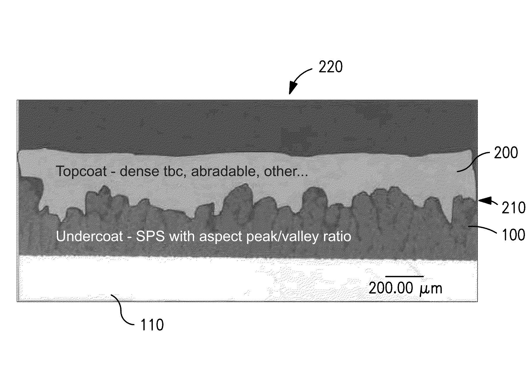
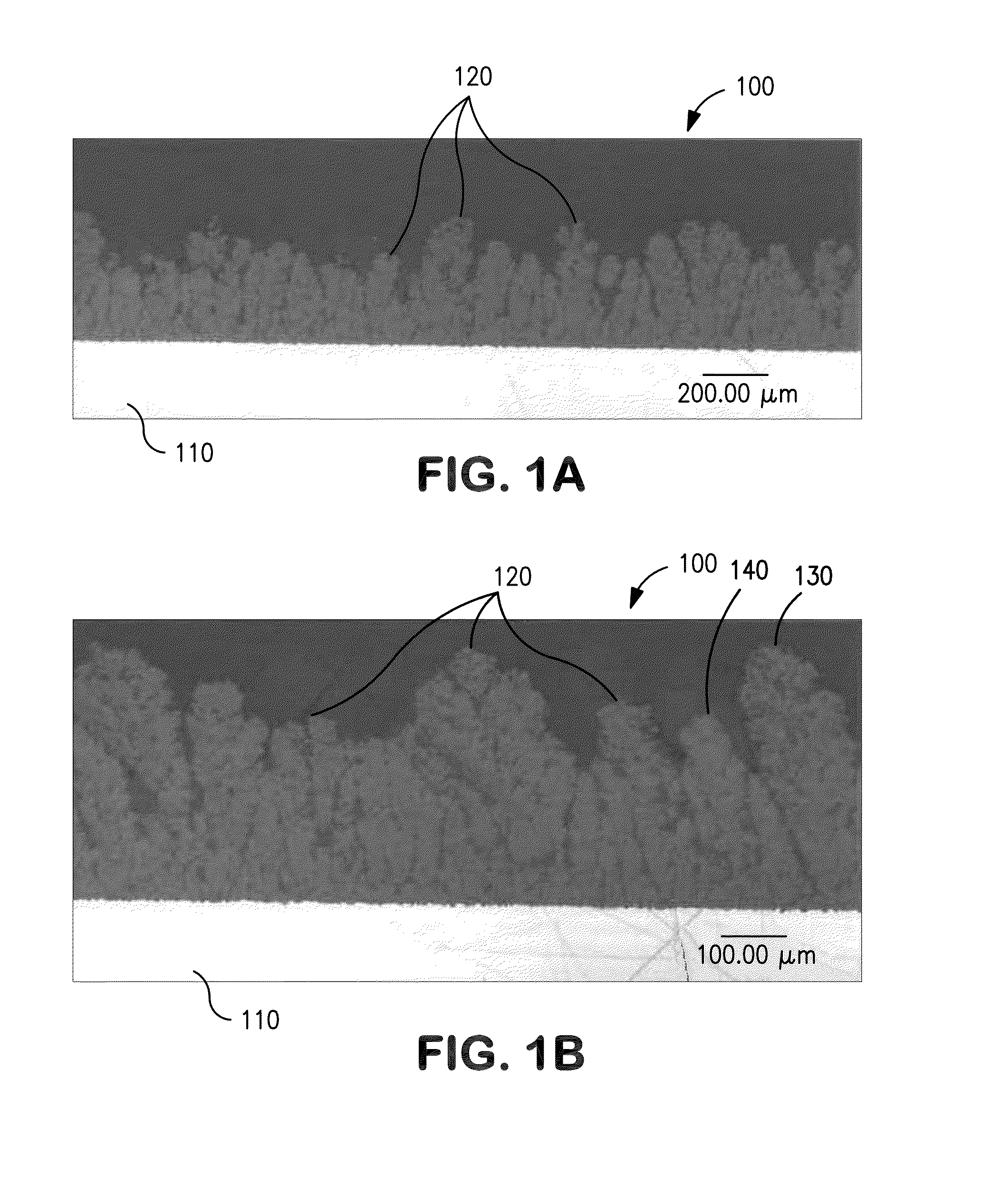
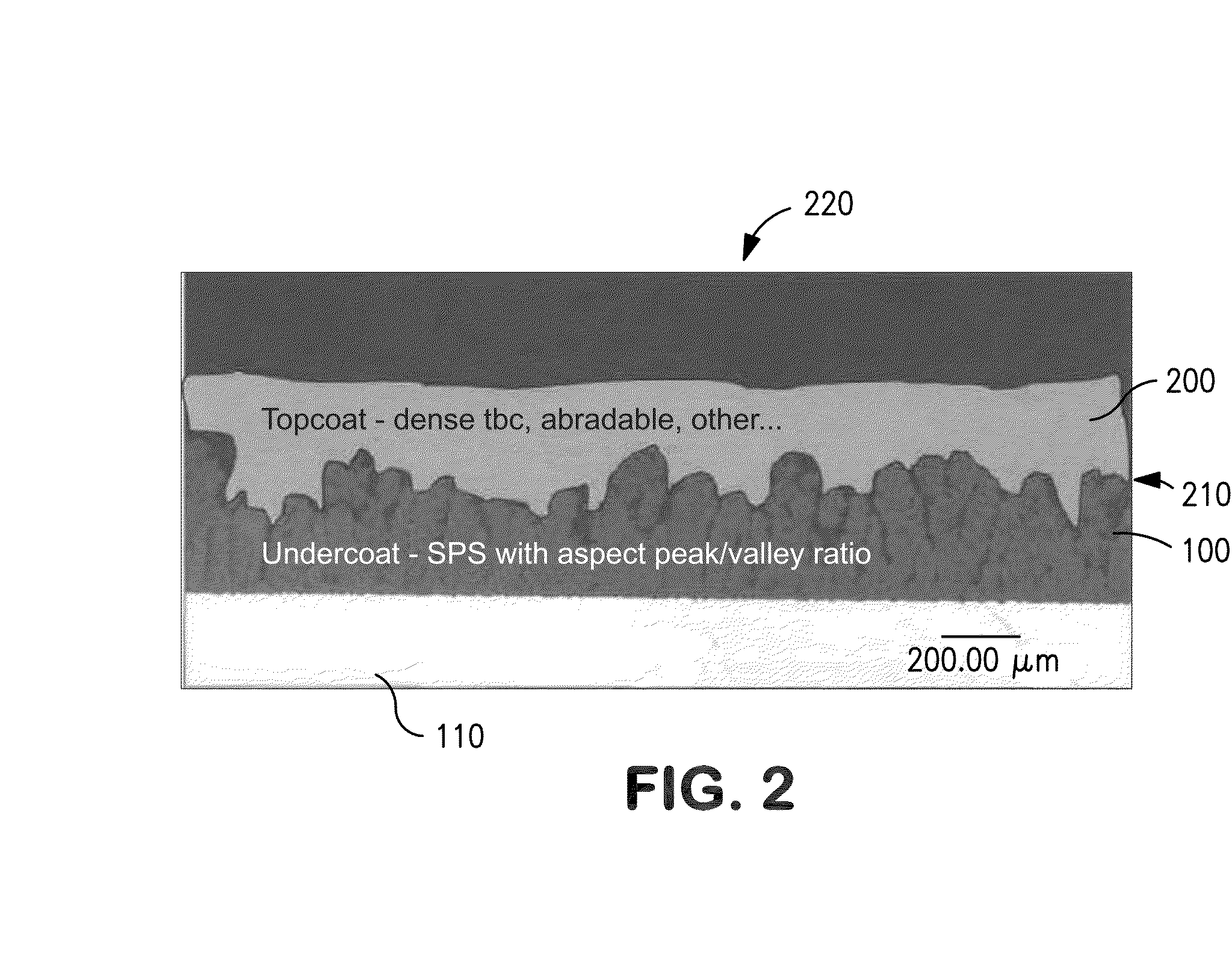
[0061]A composite coating system (designated “Columnar SPS Composite A”) was prepared as shown in FIG. 7. The undercoat layer was prepared from feedstock of 7-8 wt % yttria stabilized zirconia (YSZ). The undercoat material had a median particle diameter of about 330 nm. The undercoat material was suspended in an ethanol based suspension and then thermally sprayed onto a smooth substrate having a surface roughness Ra of about 25-40 μin. The coating thickness of the undercoat was 6-7 mil.

[0062]The topcoat layer was prepared from a feedstock material of 7-8 wt % YSZ. The top topcoat material had a median particle diameter of about 2 μm. The topcoat material was suspended in a liquid carrier of an ethanol-based suspension and then thermally sprayed onto the substrate. The coating thickness of the topcoat was 4-5 mil. The thickness of the composite coating was 10-12 mil.

[0063]The resultant composite coating system produced is shown in FIG. 7. The composite contained a ...

example 2

Composite Structure

[0067]A composite coating system (designated “Columnar SPS Composite B”) was prepared as shown in FIG. 8. The undercoat layer was prepared from a feedstock of 7-8 wt % yttria stabilized zirconia (YSZ). The undercoat material had a median particle diameter of about 330 nm. The undercoat material was suspended in an ethanol based suspension and then thermally sprayed onto a smooth substrate having a surface roughness Ra of about 25-40 μin. The coating thickness of the undercoat was 6-7 mils.

[0068]The topcoat layer was prepared from a feedstock material of 7-8 wt % YSZ dry powder having an average particle diameter between 22-62 μm. The topcoat material was thermally sprayed by atmospheric plasma spraying (APS) onto a smooth substrate surface to produce an APS Densely Vertically Cracked (DVC) topcoat. The thickness of the APS DVC topcoat was about 8 mil and the total composite coating thickness was about 14-15 mil.

[0069]The resultant composite coating system is shown...


PUM

PropertyMeasurementUnit
sizeaaaaaaaaaa
sizeaaaaaaaaaa
sizeaaaaaaaaaa

Abstract

A novel coating system is provided that allows for a single coating structure to exhibit properties previously considered mutually exclusive. A unique approach for tailoring specific properties of a coating structure as a function of location within the coating is provided with a specially designed undercoat having a columnar macrostructure and a second coating layer that is selected to be compatible with and complement the undercoat. The resultant composite coating system can maintain thermocomechanical compliance while improving various bulk and / or free surface properties of the composite coating system.

Description

FIELD OF THE INVENTION[0001]The present invention relates generally to the field of thermal barrier composite coatings utilized to protect substrate materials from high temperature and corrosive environments.BACKGROUND OF THE INVENTION[0002]Thermal barrier coatings (hereinafter, referred to as “TBC's”) applied onto a substrate are known to inhibit the flow of heat into the substrate. TBC's are commonly utilized to protect alloy components of gas turbine engines that are exposed to hot combustion gases.[0003]TBC's can be deposited by vapor processes, such as physical vapor deposition (PVD). Such PVD coatings typically are produced from process conditions designed to foster nucleation and growth of discrete, tightly packed, columnar grains which provides a compliant microstructure. The columnar grains are separated by small gaps that can relieve the stress in the coating. However, the gaps between the columns can provide pathways for penetration of contaminants which can induce corros...

Claims


Application Information

Patent Timeline
Patent Type & Authority Applications(United States)
IPC IPC(8): F01D25/00
CPCF01D25/007F01D25/005C23C28/042C23C28/048F01D5/288C23C4/11C23C4/134Y10T428/24355Y10T428/24612
Inventor PETORAK, CHRISTOPHER A.
Owner PRAXAIR ST TECH INC
Why Eureka
Try Eureka