Article assembly disassembly system

a technology for disassembly and assembly of articles, applied in the field of articles assembly and disassembly systems, can solve the problems of large number of textile based articles, which have been assembled from multiple components, and are difficult to recycle into useful products and/or be reused at the end of their useful or expected life, and many garments are difficult to recycle, so as to simplify general cleaning and prevent accidental damage. , the effect of preventing dust contamination

Active Publication Date: 2015-06-18
WEAR2GO BV
View PDF2 Cites 4 Cited by
  • Summary
  • Abstract
  • Description
  • Claims
  • Application Information

AI Technical Summary

Benefits of technology

[0043]In a preferred embodiment, the yarn containing at least one filament or yarn that it susceptible to exposure to electromagnetic radiation is covered (or sheathed) with staple fibre (e.g. cotton, viscose, lyocell, polyester, polypropylene, polyamide) so as to hide the core component. This is done by existing processes that are known in the art, for example, core-spinning, ring spinning, air-jet spinning or friction spinning. It has been found that such an arrangement facilitates the production of yarns that are compatible with high speed sewing or embroidery operations as well as providing a means of modifying the colour and appearance of the yarn. In a preferred embodiment the cover yarn has a yarn linear density of 50 dtex or more. Preferably the cover yarn is twisted in both the S-direction and Z-direction to produce a double-covered yarn assembly of balanced twist. By twisting two or more additional yarns around the yarn core, the core is mechanically protected from subsequent abrasion. Furthermore the core is also substantially hidden from view. The colour, handle, appearance, softness and general aesthetics of the final yarn is then principally dependent on the yarns twisted around the core. As a result of covering the core with yarns containing cotton, the resulting yarn surface may be soft and hydrophilic as well as being suitable for yarn colouration or chemical finishing. A particularly suitable construction for sewing thread use was produced by twisting at least two additional yarns composed of cotton around a “core” multifilament yarn or staple fibre yarn with a specific resistivity of 10−2-100ΩQ*cm. The “core” multifilament or staple fibre yarn is composed of acrylic or polyamide fibre wherein the fibres and filament contain a chemically bonded layer of copper sulphide that is proximal to the fibre / filament surface. The copper sulphide layer is of the order of 300-1000 Å (angstroms) thick. It was determined that the “core” can comprise of a Thunderon™ polyamide multifilament yarn containing a layer of copper sulphide (sulfide). This “core” yarn could be hidden by the two or more yarns twisted around it. A particularly suitable grade of core material was Thunderon™ 110 dtex / 24F.
[0046]It is preferred that the connecting means comprises one or more materials having a specific resistance within the range of 10−5-1011Ω.cm., more preferably 10−5-105Ω.cm., more preferably 10−5-100Ω.cm., more preferably 10−4-100Ω.cm., and most preferably 10−3-100Ω.cm. Pseudo-conductive materials are preferred to reduce the potential for over-heating and damage to the surrounding textile fabric whilst at the same time providing sufficient heating to deteriorate mechanical properties. Thus it is preferred that in the present invention connecting means with a resistivity of less than 10−3 Ω.cm are selected, which are not metals or metal containing. It is also preferred that in the present invention connecting means with a resistivity of greater than 100Ω.cm are selected, which exclude elemental carbon and / or carbon black and / or graphite.
[0048]Such stitch classes, without limitation, may include: 100 single thread chain stitch; 300 lock stitch; 400 multi-thread chain stitch; 500 over edge chain stitch; 600 covering chain stitches; or any combination of two or more of these stitch classes. The yarn may be used as, needle thread, bobbin thread, looper thread or any combination of these. According to the stitch class, to ensure joint failure following the exposure of the joint to electromagnetic radiation, it may be particularly advantageous to incorporate the thread susceptible to a reduction of its mechanical properties only as a bobbin thread of the bi-component stitch since the tensile strength requirements are frequently less critical for the bobbin component than for the needle-thread component where higher processing forces are encountered during manufacture of the joint. Microwave-induced failure of the lower thread component in the joint (delivered by the bobbin thread) is then the controlling factor in the mechanical failure of the bi-component joint, facilitating separation of the upper and lower components of the connection means and thus separation of the article components secured by the bi-component joint. This approach also minimizes the economic cost of the joint, since the microwave-sensitive yarn component is only required in part of the entire joint construction.
[0049]It is preferred that the mechanical property reduced on exposure to microwave and resistive or dielectric heating or a combination thereof is the tensile strength of one or more of the materials comprising the connecting means. The loss of tensile strength in one or more of the materials comprising the connection means enables that component of the connection means to fail resulting in loss of strength of the connection means and its consequential structural failure allowing disassembly to be achieved. The total reduction in tensile strength (breaking load) that is achieved as a result of microwave heating has been found to increase as the overall yarn or filament linear density (tex=weight in g of 1000 m of yarn) decreases.
[0056]The articles for disassembly may be processed through the equipment singularly or in multiples, in bales or in rigid tote bins, flexible bags or other types of container compatible with the electromagnetic i.e. microwave environment. The process may take place in batch, semi-continuous or continuous operation. Preferably, the chamber, which may be an aluminium chamber, features an inner box liner, preferably polymeric in nature e.g. manufactured from polyurethane and sized to accept a particular tote bin pre-existing in the supply chain. The liner separates the working volume of the equipment from the associated technical workings of the chamber, specifically such workings as the mode stirrer and the three microwave apertures. This feature prevents accidental damage occurring to the mode stirrer or the microwave wave guides, as well as preventing dust contamination within the wave guides / microwave apparatus and simplifying general cleaning.
[0058]The openings to the chamber may feature doors to fully seal the opening during the electromagnetic field operation; these doors may be manual, semi-automatic or fully automatic in operation. The physical configuration of these doors and the sequence of their operation may be designed as to allow batch, semi-continuous or continuous operation. In a preferred embodiment on the inner face of the door there is mounted a choke seal to prevent any leakage of microwave fields when the door is closed. To make the choke seal effective while still allowing easy and rapid manual opening and closing of the door, the door is preferably held tightly closed by means of pneumatically actuated clamps, acting across the top and bottom edges of the door. The clamps are automatically activated when the door is pushed closed, as this action engages a pair of safety interlocks, one mounted either end of the door; receiving the engaged signal from both interlocks informs the control system to close the clamps.

Problems solved by technology

The vast majority of textile based products, which have been assembled from multiple components e.g. garments, shoes, furnishings, floor coverings, quilts, mattresses, bedding, automotive airbags, seat covers and safety belts are very difficult to recycle into useful products and / or be reused at the end of their useful or expected life.
Whilst various methods exist for recycling of textile-based products, many garments are difficult to recycle due to the complexity of their structure and the presence of multiple different materials including non-textile materials used in their manufacture.
Whilst the majority of textile-based articles being directed to municipal waste such as landfill have reached the end of their useful life a significant quantity of such textile based articles have not reached the end of their useful life and could be reused or redirected for use elsewhere.
Significant quantities of clothing is rejected by retailers and brand owners because of flaws or because it is surplus to requirements or it is out of season / fashion.
In addition, although large quantities of donated clothing are collected each year, not all of this clothing is suitable for re-sale or re-use.
Many articles of corporate clothing including uniforms cannot be reused because there are potential security issues associated with the corporate identity.
At present, identifying insignia or labels cannot be easily or economically removed to reduce the risk of such security issues.
The main reason why the bulk of these articles are not reused is because they are difficult and expensive to process for the removal of labels and corporate insignia.
Removal of labels and tax tabs prior to reuse is necessary often for security reasons, but is hampered because it often has to be done manually, which is not cost-effective.
Also, the underlying fabric may be unavoidably damaged as the logo or insignia is removed.
Embroidered logos and insignia are particularly difficult to remove in a cost-effective manner without damaging the base fabric in the process.
Another problem with many textile products is the heterogeneity of the composition and methods that are used to join the integral components, which are irreversible.
When such products are shredded, these different materials become intermixed and the separation of these individual components becomes very difficult.
If an attempt is made to disassemble a conventional textile product in to its separate components by breaking stitches, seams or joints mechanically, substantial energy is required because these joints are not designed to be separated, for the same reason the separation may be incomplete due to tearing of the product due to the force involved resulting in some cross contamination of the material streams.
The cost-effective disassembly and separation of the individual components of a textile product at the end of life is therefore problematic.

Method used


Image

  • Article assembly disassembly system
  • Article assembly disassembly system
  • Article assembly disassembly system

Examples


example 1

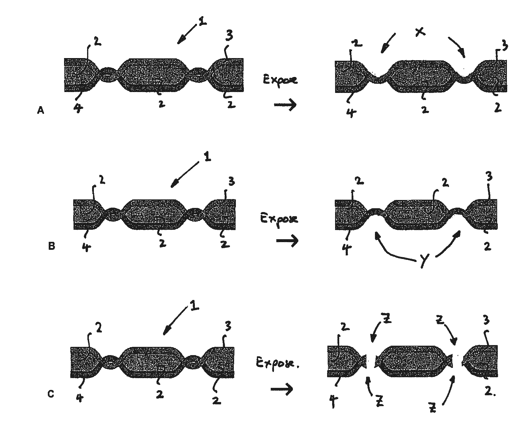
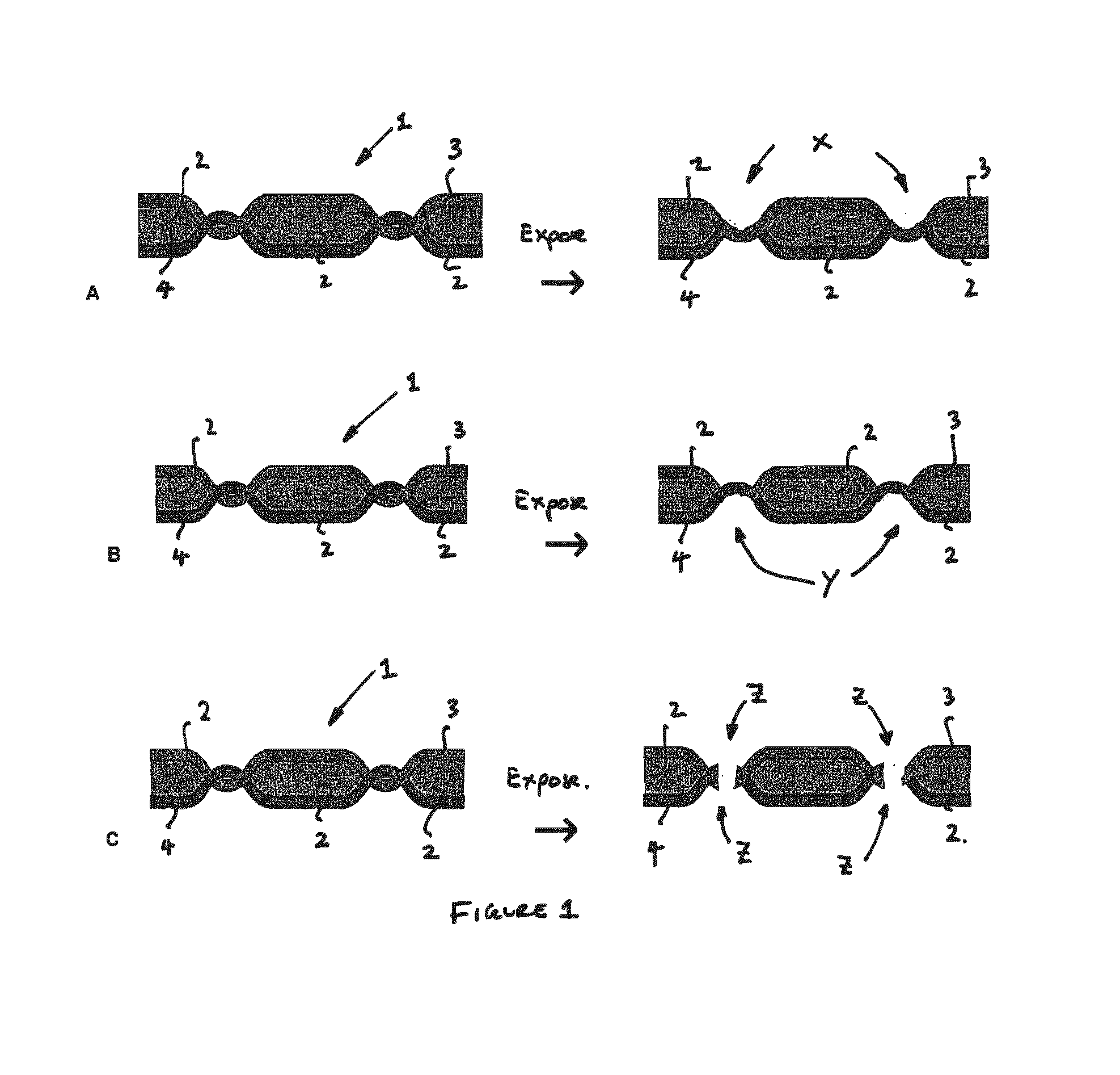
[0087]Various samples of embroidered logos, sewing yarns and backing fabric were obtained from Mathias & Sons Ltd. A yarn blend of Kevlar® / Acrylic and 50 micron steel wire (Dualtec® AISI 304L) was supplied by Saveguard Ltd, UK. Various article arrangements were prepared with this yarn and other yarns and the samples were subsequently exposed to microwave radiation in a microwave oven, (model Cookworks MM717CKA 700 Watt). The samples and conditions are as follows:[0088]a) Metallic yarn, Dualtec AISI 304L was passed through an embroidered logo from rear side using hand stitching needle. The sample was exposed to microwaves for 10-20 seconds.[0089]b) Fabric sample sewn using a lockstitch with Dualtec AISI304L50 (incorporates 50 ∥m diameter steel yarn) as the understitch and 100% PET sewing yarn as the upper thread. This sample was exposed to microwaves for 5 seconds.[0090]c) Backing fabric lock stitched using Dualtec AISI304L50 as the understitch and 100% PET sewing yarn as upper threa...

example 2

[0094]A commercially available yarn, Thunderon®, (Nihon Sanmo Dyeing Co., Ltd), was used to form a stitch based connection means for various textile based articles. Thunderon® is an acrylic or polyamide fibre or filament that contains a chemically bonded layer of copper sulphide. The fibre diameter is ˜4 μm, the thickness of its conductive layer is 300-1000 Å (angstroms) and it has a specific resistivity of 10−2-100Ω.cm. A 110 dtex polyamide Thunderon® yarn was used as the bobbin thread in 301 lock stitch and 406 construction cover stitch to manufacture various garments, such as shirts, trousers, T-shirts, and jackets.

[0095]The prepared samples with interlock and overlock seams produced with

[0096]Thunderon® monofilament yarn had similar seam strengths to samples stitched with standard threads. The seam strength of seams containing Thunderon® yarn was similar to the standard samples. Five shirts and five pairs of trousers were successfully produced using commercial garment assembly t...

example 4

[0100]Polyamide multifilament yarns containing a layer of copper sulphide were obtained with linear densities of 121 dtex / 24F (filaments) and ca. 110 dtex / 24F.

[0101]The specific resistance of these yarns was ca. 10−1-10−2Ω.cm and the filament tenacity was ca. 4.5 g / den (grams per denier). The yarn strength enabled these yarns to be utilized directly in sewing operations without end breakages. However, to facilitate high speed sewing or embroidery operation as well as provide a means of modifying the colour and appearance of the yarn, plied yarn assemblies were constructed. Using a hollow spindle up-twisting machine the 110 dtex / 24F yarn was twisted with a 50 dtex textured polyester yarn in both the S-direction and Z-direction to produce a double-covered yarn assembly of balanced twist. A yarn linear density of 50 dtex was approximately the minimum required to satisfactorily disguise the core yarn component during the twisting operation. Thus, by twisting two or more additional yarns...


PUM

PropertyMeasurementUnit
frequencyaaaaaaaaaa
frequencyaaaaaaaaaa
frequencyaaaaaaaaaa

Abstract

There is described a system, article, method, connectors and apparatus for article reuse or recycling, which system including the assembling of an article from at least two components at least one of which has a textile material brought into communication with each other through one or more connectors and the subsequent disassembling of the article and use of one or more of the components in the assembling stage. The assembled article is susceptible to automatic or semi-automatic disassembly through one or more of its connectors being susceptible to a reduction in one or more mechanical properties under exposure of the article to electromagnetic energy especially microwave. The article may be a garment that has joins stitched with a microwave susceptible yarn. The yarn is ideally manufactured from pseudo-conductive materials and is metal free.

Description

FIELD OF INVENTION[0001]The present invention is concerned with a system for the assembly and disassembly of articles and in particular is concerned with a process for the assembly and disassembly of textile based articles and with equipment and articles for such an assembly and disassembly process.BACKGROUND ART[0002]The vast majority of textile based products, which have been assembled from multiple components e.g. garments, shoes, furnishings, floor coverings, quilts, mattresses, bedding, automotive airbags, seat covers and safety belts are very difficult to recycle into useful products and / or be reused at the end of their useful or expected life. The majority of these products are either downcycled into low value products or discarded to municipal waste. Some garments, if in satisfactory condition may be suitable for reuse without additional re-manufacture and may be sold via charity shops or exported to developing countries where they are reused.[0003]A common example of recycl...

Claims


Application Information

Patent Timeline
Patent Type & Authority Applications(United States)
IPC IPC(8): D06H7/22B02C23/00
CPCB02C23/00D06H7/221B29K2913/00B29K2313/02B29L2031/726B29B17/02D06H7/225B29B17/0026Y02W30/62A41D2300/50
Inventor RUSSELL, STEPHEN JOHNREA, CHARLESBELL, ROBERT STUART ELLISMALONEY, NORMAN
Owner WEAR2GO BV
Why Eureka
Try Eureka