
Carbon nanomaterials based real time radiation dosimeter

a carbon nanomaterial and radiation dosimeter technology, applied in nanotechnology, chemical vapor deposition coating, inorganic chemistry, etc., can solve the problems of not being able to realize real time measurement, requiring complex calibration, and requiring wide and complex physical and dosimetric procedures

Inactive Publication Date: 2015-06-18
UNIVERSIT DEGLI STUDI DI SALERNO
View PDF15 Cites 5 Cited by
  • Summary
  • Abstract
  • Description
  • Claims
  • Application Information

AI Technical Summary

Benefits of technology

The invention is about a new type of radiation dosimeter that uses carbon nanomaterials, such as carbon nanotubes, to measure the absorbed dose of ionizing radiation in real-time. The dosimeter has electrodes made of carbon nanotubes, which are placed between two plates and can be used in various medical applications. The new dosimeter has several advantages over existing dosimeters, including higher accuracy, practicality, and reliability. It can be operated at a small voltage and has better spatial resolution, making it suitable for in vivo dose measurements. The method to produce the electrodes is also provided. The technical effect of the invention is to provide an improved electrode for an ionization chamber that can measure the absorbed dose of ionizing radiation accurately and easily.

Problems solved by technology

The clinical use of ionizing radiation to obtain a necrosing or cytotoxic radiobiological effect on tumoral lesions requires wide and complex physical and dosimetrical procedures.
Moreover, they do not allow to realize real time measurement and they require a complex calibration.
MOSFET dosimeters overcome the correction factors required for diodes and they can be used for the measurement of delivered dose in patient, but they are expensive and they destroy after few treatments.
They are characterized by high accuracy, practicality and reliability, but they require a high bias voltage to achieve an acceptable collection of charges and have a relative large physical size which limits their spatial resolution.
These drawbacks limit their application for in vivo dose measurements.
Moreover, no experimental result is reported in some application field and in particular no application in the field of dosimetry is proposed.

Method used


Image

  • Carbon nanomaterials based real time radiation dosimeter
  • Carbon nanomaterials based real time radiation dosimeter
  • Carbon nanomaterials based real time radiation dosimeter

Examples


example 1

[0041]In the first example, a ionization chamber, comprising an aluminium cathode and a carbon nanotubes forest based anode, is proposed as dosimeter (FIG. 3). In particular, a forest of vertically aligned MWCNTs were grown by CCVD on a silicon substrate.

[0042]To synthesise MWCNTs, nichel ferrite nanoparticles NiFe2O4 were first prepared by a wet chemistry approach (FIG. 4). In particular, Ni(acac)2 (1 mmol), Fe(acac)3 (1 mmol), 1.2 hexadecanediol (10 mmol), oleic acid (6 mmol), oleylamine (6 mmol), and phenyl ether (20 mL) were mixed and magnetically stirred under nitrogen flow. The mixture was heated to 265° C. for 30 min. Then, the black-brown mixture was cooled to room temperature and ethanol was added under ambient condition; the black material was precipitated and separated via centrifugation. The products were dispersed in hexane and stored in a vial.

[0043]The nanoparticles, dispersed in hexane, were patterned by microcontact printing using a PDMS stamp on silicon wafer SiO2 / ...

example 2

[0051]In the second example, the proposed dosimeter is a ionization chamber comprising an aluminium cathode and graphene layers based anode (FIG. 9).

[0052]Graphene layers were prepared on 25 μm copper foil by CCVD of methane diluted in nitrogen.

[0053]The synthesis was performed in isothermal conditions at 950° C., 100 (stp)cm3 / min flow rate, after 40 min pre-treatment of the foil from room temperature up to the synthesis temperature. The average cooling rate after the synthesis was 2° C. / min.

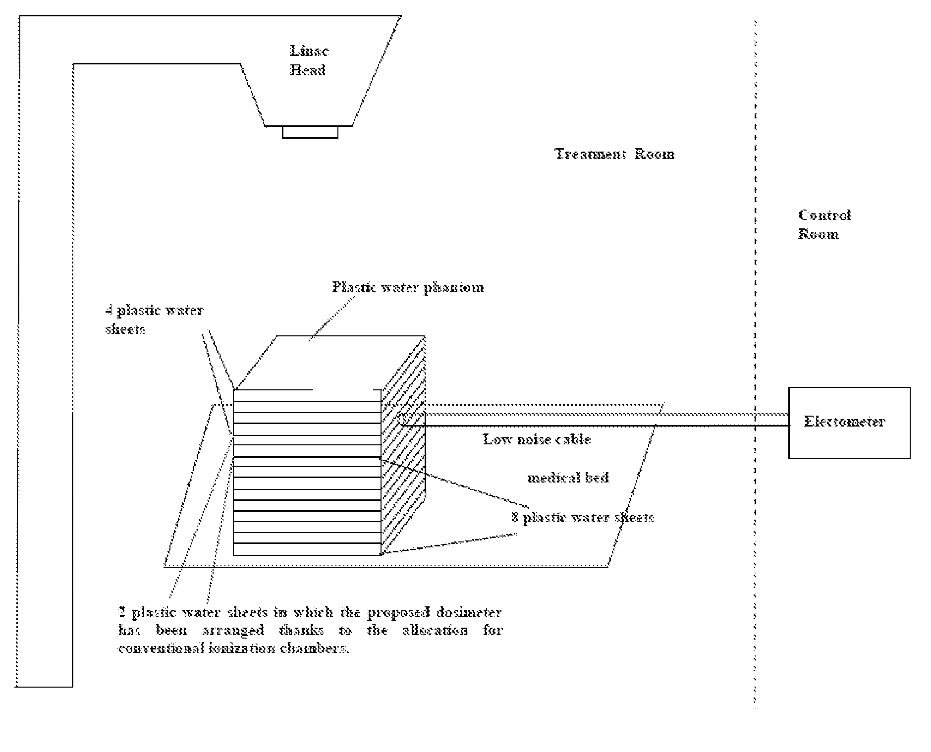
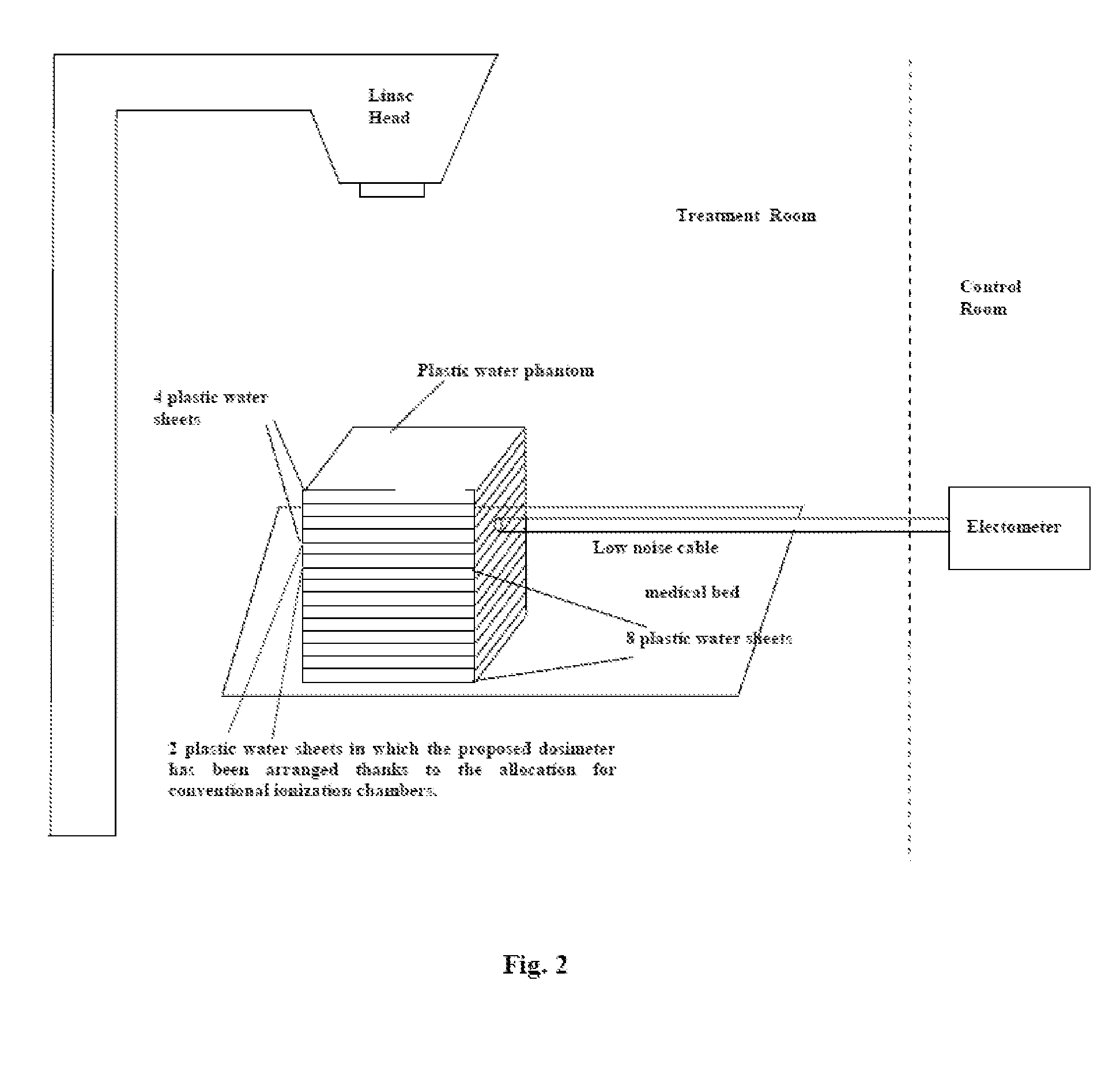
[0054]The experimental irradiation set-up was as in example 1 (FIG. 2).

[0055]The dosimeter was irradiated with 21 MU, 50 MU and 105 MU. A bias voltage of 310 V was applied between the electrodes which were distant 12 mm. Also in this case, the collected charge shows an excellent linear dependence on dose (FIG. 10).


PUM

PropertyMeasurementUnit
Electric potential / voltageaaaaaaaaaa
Distanceaaaaaaaaaa

Abstract

A real time radiation dosimeter includes a first electrode and a second electrode, such as cathode and anode electrodes. The second electrode is based on carbon nanomaterials, such as carbon nanotubes bucky paper, carbon nanotubes forest and graphene film. The dosimeter is connected to an electrometer, able to apply a bias voltage between the electrodes and to measure the collected charge. The manufactured detectors display an excellent linear response to dose. The dosimeter with nanotubes forest is able to collect charge also to zero voltage, allowing in vivo applications. The use of nanomaterials allows a miniaturized version of dosimeters.

Description

FIELD OF THE INVENTION[0001]The invention relates to a real time radiation dosimeter having electrodes based on carbon nanomaterials, such as carbon nanotubes bucky paper, carbon nanotubes forest and graphene film.[0002]In the present description the definition of carbon nanomaterials is used generically to mean carbon based nanostructured materials.[0003]The invention further relates to a method of producing these electrodes.DESCRIPTION OF THE PRIOR ART[0004]The clinical use of ionizing radiation to obtain a necrosing or cytotoxic radiobiological effect on tumoral lesions requires wide and complex physical and dosimetrical procedures. In particularly, it is necessary to calculate accurately the absorbed dose optimizing its delivery in order to treat the tumor saving the surrounding healthy tissues. Delivery parameters of a prescribed dose are determined during treatment planning which is performed on dedicated computers using specialized treatment planning software. It is crucial t...

Claims


Application Information

Patent Timeline
IPC IPC(8): G01T1/14G01T1/185G01T1/02C23C16/26
CPCG01T1/14G01T1/026G01T1/185C23C16/26B82Y15/00B82Y30/00C01B2202/06C01B2202/08B82Y40/00C01B32/162
Inventor ALTAVILLA, CLAUDIACIAMBELLI, PAOLOFUNARO, MARIAPROTO, ANTONIOSARNO, MARIA
Owner UNIVERSIT DEGLI STUDI DI SALERNO
Learn More