Heat-insulating structure of member facing engine combustion chamber, and process for producing same

a technology of heat-insulating structure and engine, which is applied in the direction of machines/engines, mechanical equipment, chemical coatings, etc., can solve the problems of cracks and peeling in the heat-insulating layer, ceramic sintered body has not been put into practical use especially, and the adhesion between particles in the zirconia-based layer is inferior to that of the cermet-based layer, so as to reduce the deformation of the heat-insulating layer and reduce the pre-ign

Inactive Publication Date: 2015-07-23
MAZDA MOTOR CORP
View PDF5 Cites 30 Cited by
  • Summary
  • Abstract
  • Description
  • Claims
  • Application Information

AI Technical Summary

Benefits of technology

[0037]In the heat-insulating structure for the engine combustion chamber of the present invention, the plating film is bonded to the heat-insulating layer body with the Si-based oxide of the hollow particles interposed therebetween. Thus, the silicone-based resin and the hollow particles achieve desired thermal insulation, and occurrence of cracks and peeling can be advantageously reduced. The plating film can reduce deformation of the heat-insulating layer due to combustion pressure, fuel impregnation in the silicone-based resin, dissolution of the silicone-based resin, and a cooling loss, and also reduces pre-ignition of the engine and a heat loss of the silicone-based resin.
[0038]In a case where the silicone-based resin is a silicone-based resin composition including a cage silsesquioxane structure, the heat-insulating layer is made of a material having a small difference in coefficient of thermal expansion from the engine member.
[0039]Thus, occurrence of cracks and peeling due to the difference in coefficient of thermal expansion between the heat-insulating layer and the engine member can be reduced. In addition, a heat-insulating layer having a high strength and a molecular structure that has a low cross-linking density and is not easily deformed can be obtained, and deformation due to, for example, combustion pressure can be reduced. In addition, occurrence of cracks and peeling in the heat-insulating layer can be reduced, and fuel impregnation is also reduced.
[0040]In the method for producing a heat-insulating structure for an engine combustion chamber, a heat insulator layer including the silicone-based resin and hollow particles containing the Si-based oxide is formed on the combustion chamber wall surface of the engine member, the surface of the heat insulator layer is heated such that Si-based oxide is generated through oxidation of the silicone-based resin in at least part of the surface of the heat insulator layer, and then the catalytic metal is added to the surface of the heat insulator layer. Thus, Si-based oxide derived from the silicone-based resin and / or hollow particles serves as a substrate of the catalytic metal. In electroless plating, the plating metal is deposited on the surface of the heat insulator layer using the catalytic metal as nuclei. As a result, the heat-insulating layer including the plating film in the surface thereof can be obtained.

Problems solved by technology

In application as a heat-insulating layer, however, the ceramic sintered body was faced with the problem of occurrence of cracks and peeling in the heat-insulating layer due to thermal stress or thermal impact.
Thus, the ceramic sintered body has not been put into practical use especially for a heat-insulating layer in a relatively large portion such as a top face of a piston, an inner peripheral surface of a cylinder liner, and a lower face of a cylinder head.
This use, however, was intended to increase the abrasion resistance, and was not intended to increase heat insulation.
However, adhesion among particles in a zirconia-based layer is inferior to that of a cermet-based layer, and cracks easily occur due to, for example, thermal stress and fatigue caused by repetitive mechanical stress.

Method used


Image

  • Heat-insulating structure of member facing engine combustion chamber, and process for producing same
  • Heat-insulating structure of member facing engine combustion chamber, and process for producing same
  • Heat-insulating structure of member facing engine combustion chamber, and process for producing same

Examples


first embodiment

Heat-Insulating Structure of Engine Member of First Embodiment

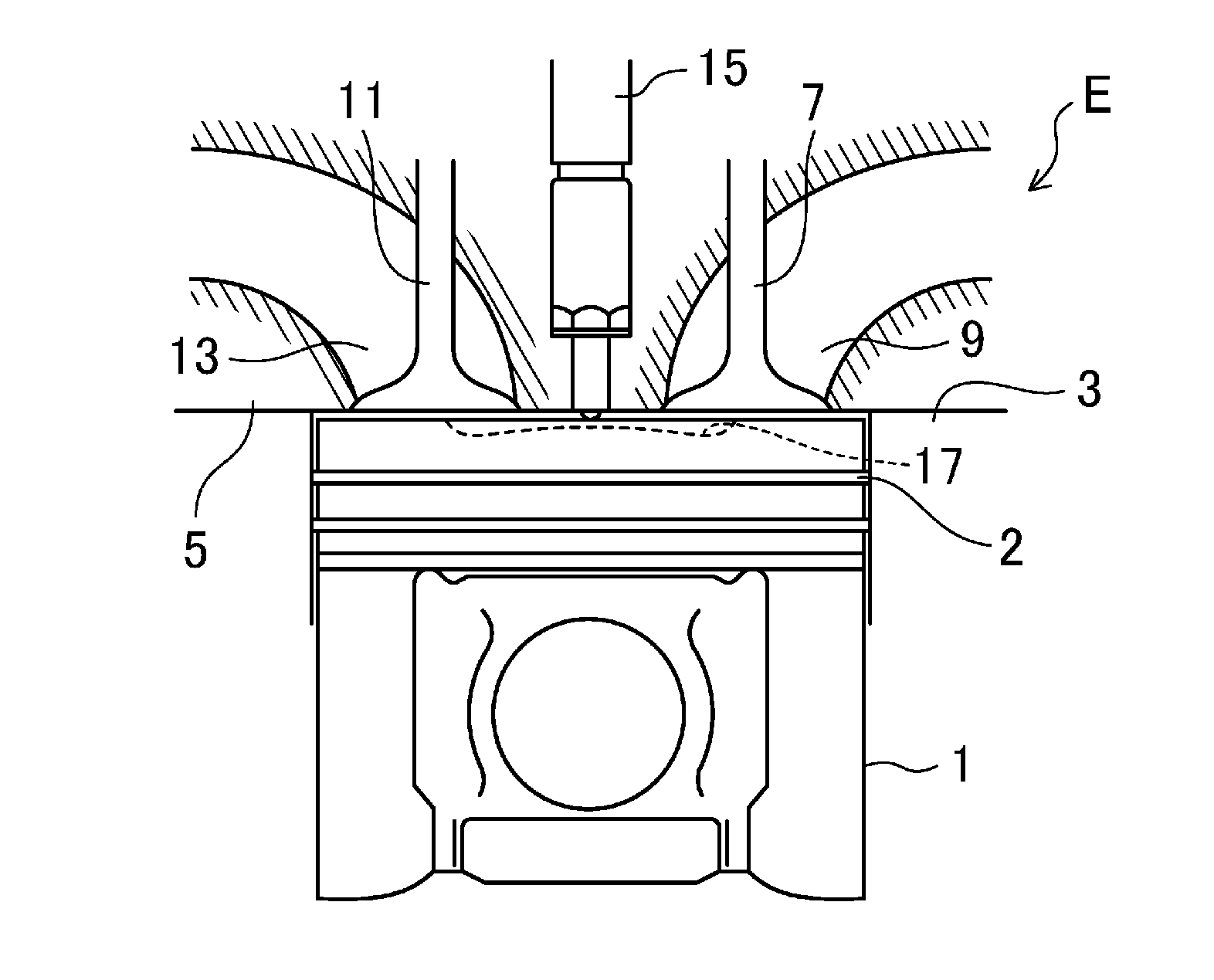
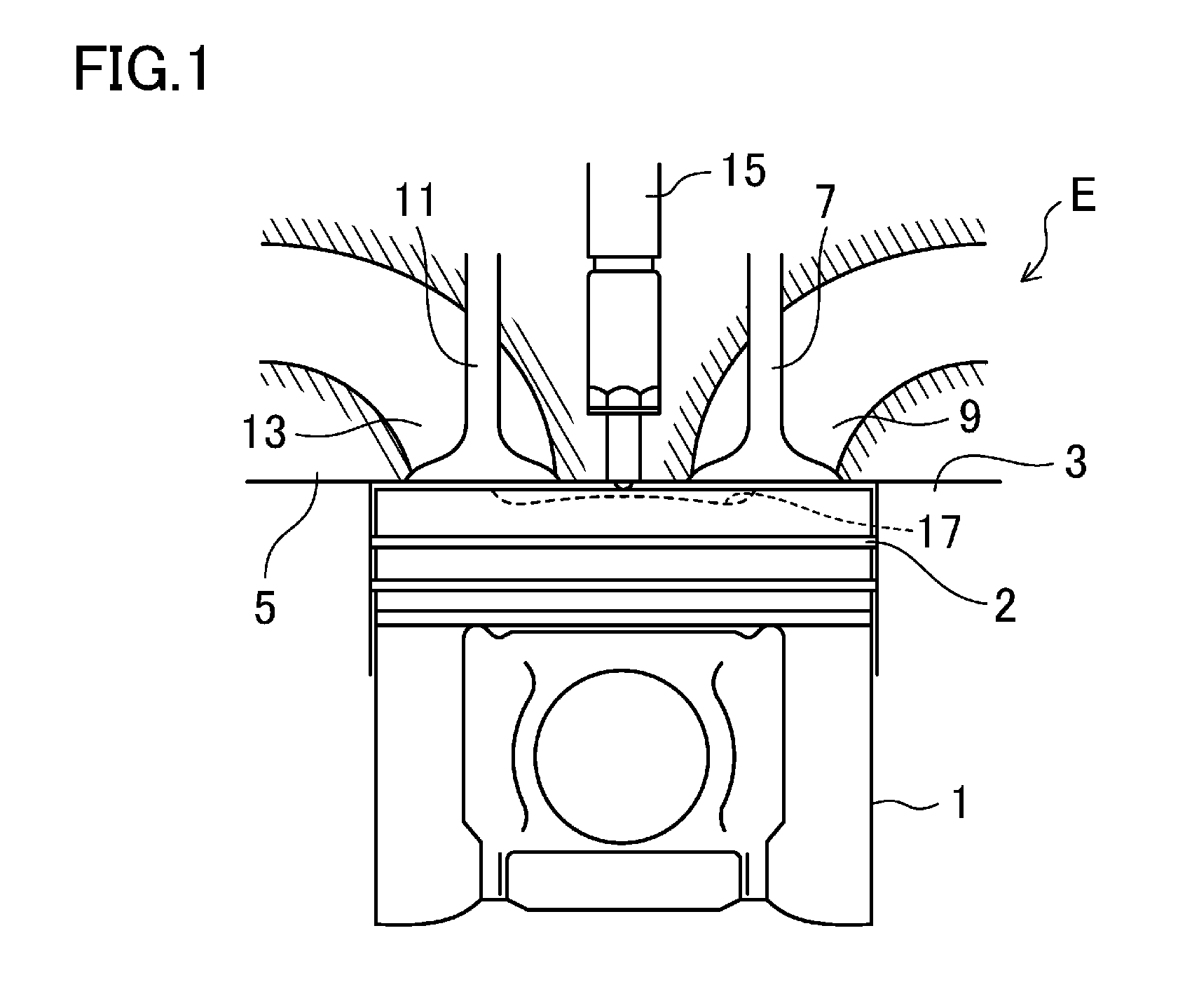
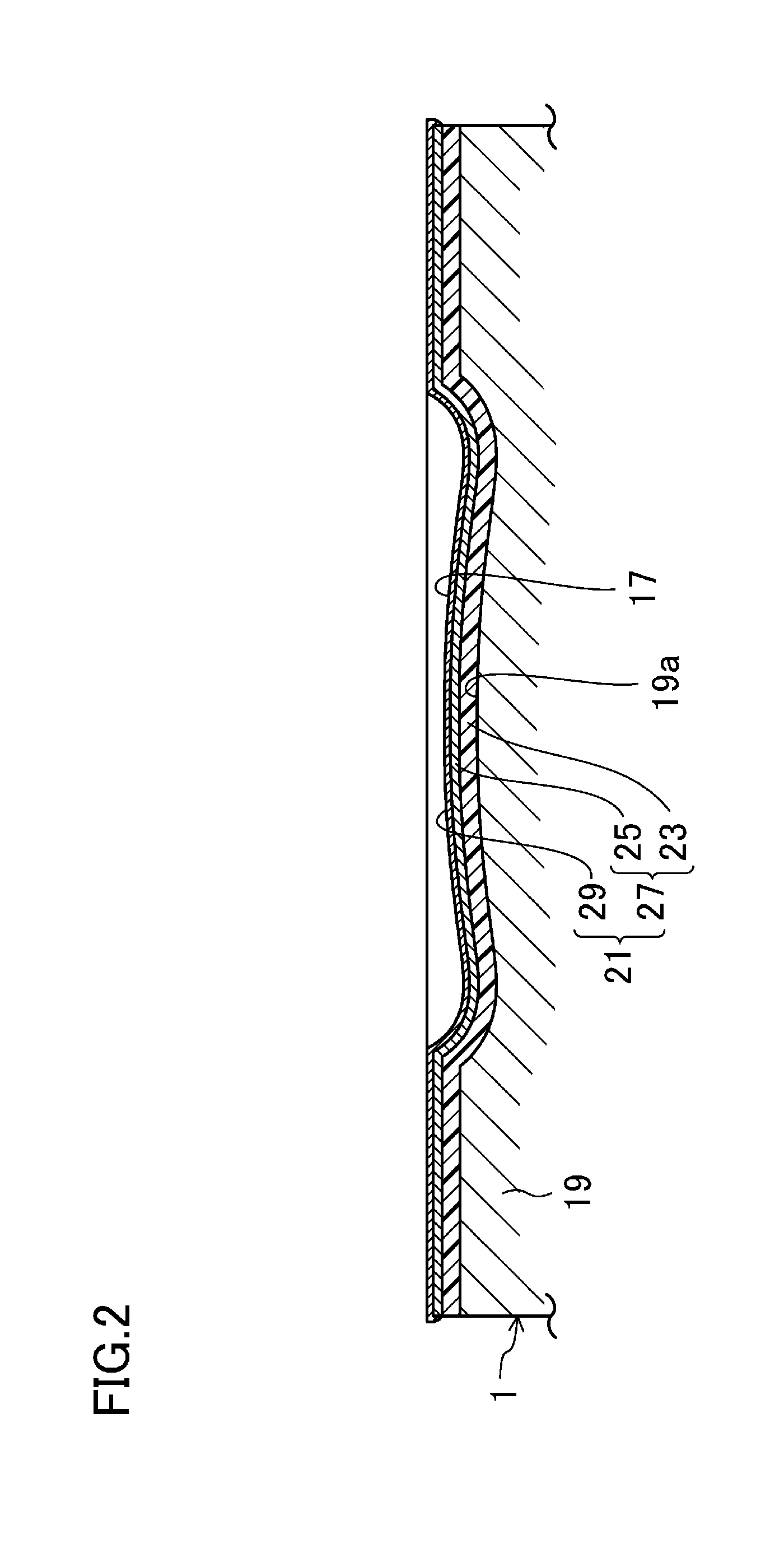
[0052]To enhance heat insulation of the engine, a heat-insulating layer 21 is formed on the top face (i.e., the face facing the engine combustion chamber) of a piston body 19 serving as an engine member, as illustrated in FIG. 2. Although not shown, heat-insulating layers similar to those on the top face of the piston 1 are formed on the surfaces of engine members, i.e., the cylinder block 3, the cylinder head 5, the intake valve 7, and the exhaust valve 11, facing the engine combustion chamber.

[0053]The cavity 17 is formed in the center of a top face 19a of the piston body 19. The heat-insulating layer 21 includes a heat-insulating film 27 as a heat-insulating layer body and a plating film 29 covering the entire surface of the heat-insulating film 27. The heat-insulating film 27 includes a base layer 23 having a low thermal conduction and covering the entire top face 19a of the piston body 19 and a surface layer 25 havin...

second embodiment

Heat-insulating Structure of Engine Combustion Chamber of Second Embodiment

[0077]Similarly to the first embodiment, in a heat-insulating structure of an engine combustion chamber according to a second embodiment, a heat-insulating layer is formed on, for example, the top face of a piston serving as a member constituting the engine combustion chamber. A specific example of this heat-insulating structure will be described with reference to FIG. 5.

[0078]As illustrated in FIG. 5, a heat-insulating layer 43 including a silicone-based resin composition is formed on the top face of a piston 1 constituting an engine combustion chamber and on a part of the outer peripheral surface of the piston 1 closer to the top face than a piston ring groove 41. The heat-insulating layer 43 includes hollow particles 31 in order to reduce thermal conductivity thereof, and also includes a plating film (not shown) in the surface thereof. The presence of such a heat-insulating layer 43 can reduce a cooling lo...

example 1

[0100]First, 12.8 g of tetramethyldisiloxane, 150 g of toluene, and 10 g of methanol were placed in a 3-neck glass flask provided with a stirrer and a thermometer and were mixed together. The resulting mixture solution was cooled to 5° C., and while the mixture solution was being stirred, 17.4 g of 69% nitric acid was dropped into the mixture solution in small portions. Thereafter, the mixture solution was returned to room temperature, and while the mixture solution was being stirred, a solution in which 50.0 g of a cage silicate compound (tetramethyl ammonium-T8-silsesquioxane: SI06696.9 produced by GELEST, inc.) was dissolved in 50.0 g of methanol was dropped for one hour. The mixture solution was stirred for four hours at room temperature, and then an aqueous layer was separated, and an organic layer was washed three times with 100 g of water. Then, the organic layer was subjected to evaporation to dryness, thereby obtaining white crystal of a compound expressed as formula 6. In ...


PUM

PropertyMeasurementUnit
temperatureaaaaaaaaaa
particle sizeaaaaaaaaaa

Abstract

A heat-insulating layer exhibiting high resistance to cracks, peeling, deformation, and gasoline and high heat insulation is obtained on the wall surface of an engine member (19). First, a heat insulator layer including a silicone-based resin and hollow particles containing a Si-based oxide is formed on a wall surface of the engine member (19). Then, Si-based oxide is produced through oxidation of a silicone-based resin in at least part of the surface of the heat insulator layer by heating the surface of the heat insulator layer. Thereafter, a catalytic metal is added to the silicone-based resin in the surface of the heat insulator layer and/or Si-based oxide derived from the hollow particles. Using the catalytic metal as nuclei, electroless plating is performed. In this manner, a heat-insulating layer (21) in which the surface of the heat-insulating film (27) is covered with a plating film (29) is obtained.

Description

TECHNICAL FIELD[0001]The present invention relates to a heat-insulating structure of a member facing an engine combustion chamber and a method for producing the structure.BACKGROUND ART[0002]As a method for increasing a thermal efficiency of an engine, the technique of providing a heat-insulating layer on a surface facing a combustion chamber of an engine was proposed in the 1980s (see, for example, Patent Document 1). Since then, a heat-insulating layer of a ceramic sintered body and a heat-insulating layer of a flame-sprayed layer containing ZrO2 particles showing low thermal conductivity have been proposed.[0003]In application as a heat-insulating layer, however, the ceramic sintered body was faced with the problem of occurrence of cracks and peeling in the heat-insulating layer due to thermal stress or thermal impact. Thus, the ceramic sintered body has not been put into practical use especially for a heat-insulating layer in a relatively large portion such as a top face of a pi...

Claims


Application Information

Patent Timeline
Patent Type & Authority Applications(United States)
IPC IPC(8): F02B23/08C23C18/18C23C18/31
CPCF02B23/08C23C18/1831C23C18/31F02B77/11F02F1/18F02F3/10F05C2251/048Y02T10/12
Inventor NANBA, SATOSHIKADOSHIMA, SHINJIKATSURA, DAIJISAKATE, NOBUOYAMANE, TAKAKAZUTAKAMI, AKIHIDE
Owner MAZDA MOTOR CORP
Why Eureka
Try Eureka