Ion source, ion gun, and analysis instrument

a technology of ion gun and analysis instrument, which is applied in the direction of instruments, particle separator tube details, separation processes, etc., can solve the problems of high damage to samples, low secondary ion yield, and high damage due to sputtering, so as to reduce damage to a level acceptable

Active Publication Date: 2015-07-23
ULVAC PHI INC
View PDF2 Cites 14 Cited by
  • Summary
  • Abstract
  • Description
  • Claims
  • Application Information

AI Technical Summary

Benefits of technology

[0031]It is an object of the present invention to achieve depth profile analysis for various types of samples made of organic and inorganic materials and a composite thereof in various types of surface analysis, while suppressing damage to a acceptable level.

Problems solved by technology

In the surface analysis, argon ion (Ar+) is the most common ion species for sputtering, but it is known that the occurrence of damage due to the sputtering is high.
Some of them can be reduced to a small beam in the order of several tens nanometer, but the occurrence of large damage to a sample is a common drawback.
In addition, if these ions are used as a primary ion source, secondary ion yield is very low, and secondary ion generation efficiency is low.
On the other hand, because a target sample surface and its vicinity are significantly damaged, application of the conventional system to a biological material is difficult; and nondestructive observation of molecule ions is difficult; specifically, the sample receives large fragmentation, and a surface of the sample is decomposed and polymerized.
However, the following phenomena are caused: (1) an inorganic material is contaminated with a carbon component derived from C60; (2) craters are generated in a surface of the material so that surface destruction occurs; (3) a biological sample or the like is significantly damaged; and (4) the secondary ion yield is low in the SIMS, and when the beam diameter is decreased, ionic strength is weakened so that utility value as the SIMS is deteriorated (particularly in an organic material).
However, for an inorganic material (such as a ceramic material) that is relatively hard, the sputtering speed is extremely slow so that it is not practical.
Therefore, a range of the sample types to be analyzed is inevitably limited to mainly organic industrial materials.
In addition, when the GCIB is used as the primary ion source in the secondary ion mass spectroscopy method, it is known that the secondary ion yield thereof is low; and hence, it is not practical when used for improving sensitivity in the secondary ion mass spectroscopy method.
In this case, the cluster ions generated in the atmosphere inevitably collide with gas molecules in the atmosphere so that many ions are scattered.
Therefore, the amount of ions that are actually transported to the vacuum side and can be effectively used is small; and in addition, downsizing of the cluster ion (fission of the cluster) also occurs due to vaporization in the atmosphere side.
Consequently, it becomes difficult to stably obtain the ion beam, and it is also difficult to decrease the beam size to be small.
On the other hand, a differential pumping system for evacuating the separated vacuum chamber also becomes large in scale which causes difficulty when in use.
Consequently, a practical ion source that can support various types in etching layer-by-layer without damaging a surface of the sample after irradiation has not been developed yet, and an ion source succeeding in dramatic improvement of sensitivity in the secondary ion mass spectroscopy method has also not yet been developed.
However, the droplet cluster ion generated in the atmosphere is downsized due to Rayleigh fission that occurs when Coulomb repulsion of itself exceeds surface tension of the droplet.
Further, the droplet cluster ions inevitably collide with gas molecules in the atmosphere so that many ions are scattered.
Therefore, an arcing phenomenon is apt to occur in the vacuum chamber 710, and hence it is difficult to obtain the droplet cluster ion beam.
Therefore, the first and second vacuum evacuating devices 729a and 729b for evacuating the inside space of the vacuum chamber 710 are required to be large ones; and hence, difficulty arises when they are used in that they occupy large areas and in terms of cost.
Hence, the conventional technology is of little practical use.

Method used


Image

  • Ion source, ion gun, and analysis instrument
  • Ion source, ion gun, and analysis instrument
  • Ion source, ion gun, and analysis instrument

Examples


first embodiment

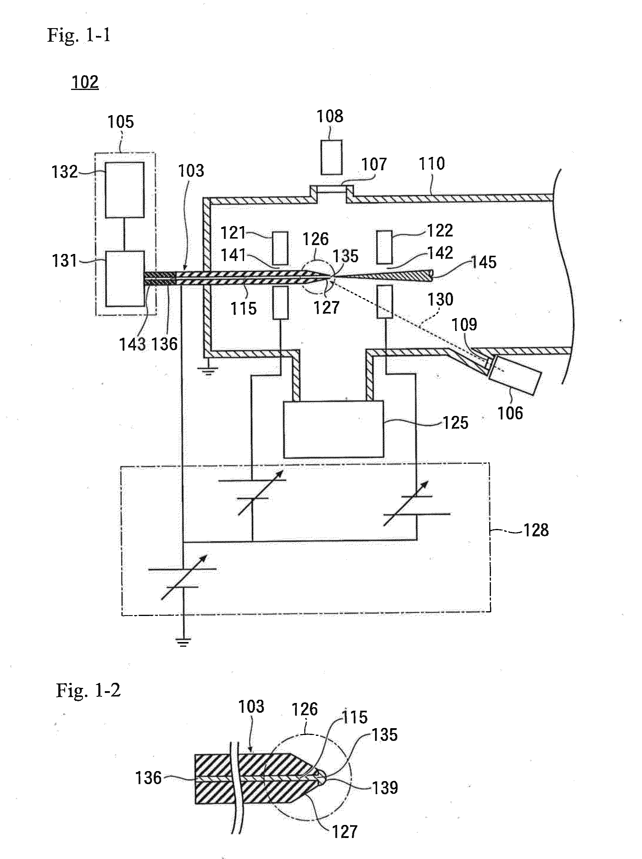
[0113]FIG. 1-1 illustrates an ion source 102 of the present invention.

[0114]This ion source 102 indicates the use of super large droplet cluster ions (containing a plurality of atoms and molecules in particles having charges), and includes a vacuum chamber 110 and an ionization liquid supply device 105.

[0115]An emission tube 103 is penetrated into a wall of the vacuum chamber 110. One end of the emission tube 103 is positioned outside the vacuum chamber 110; and a distal end portion 126 as the other end is positioned inside the vacuum chamber 110.

[0116]Inside the emission tube 103, a thin tube 115 is formed.

[0117]The ionization liquid supply device 105 includes a liquid storing portion 132 and a liquid feeding pump 131 connected to the liquid storing portion 132.

[0118]The thin tube 115 is connected to a liquid supply pipe 143 at a base part 136 outside the vacuum chamber 110; and the liquid supply pipe 143 is directly connected to the liquid feeding pump 131. The liquid storing port...

second embodiment

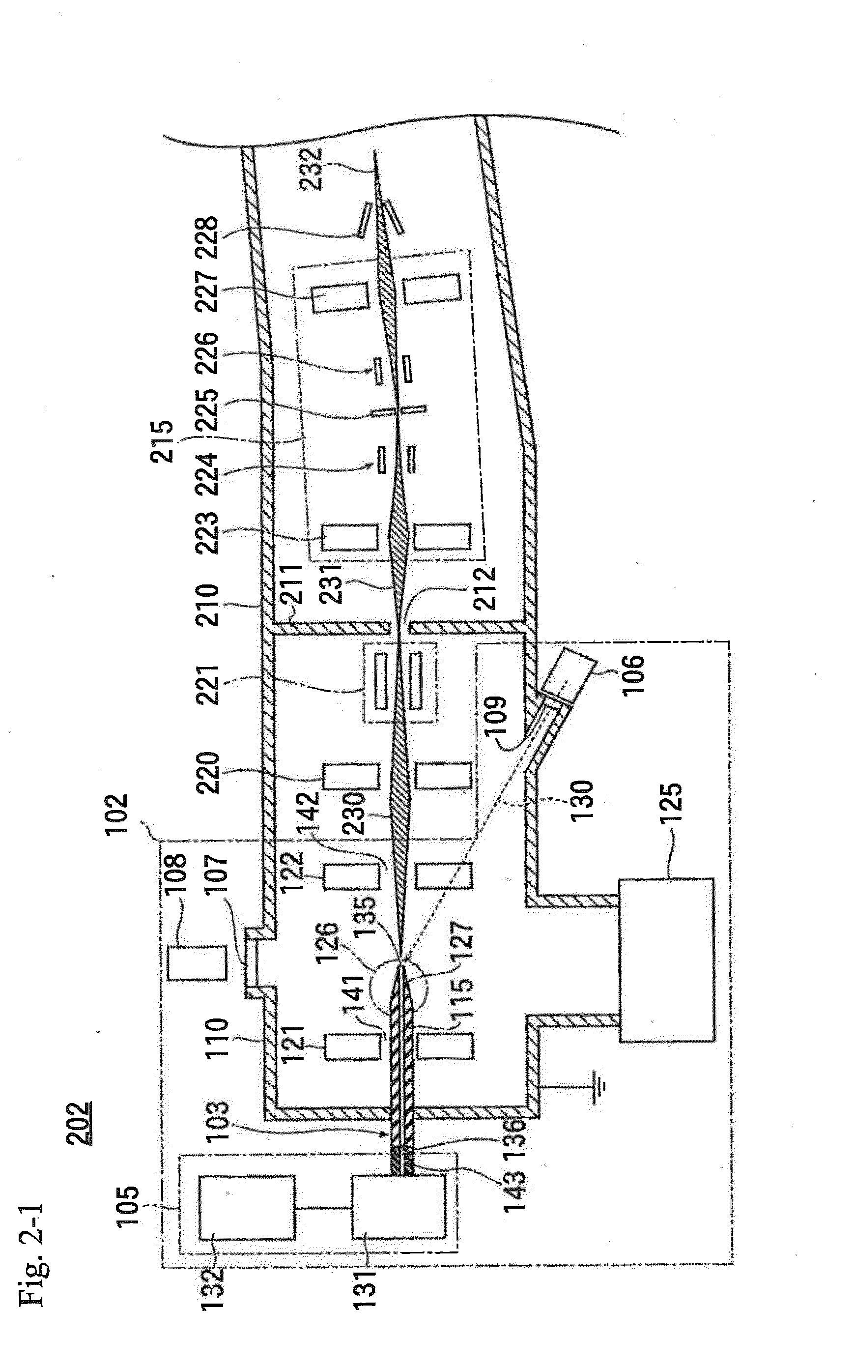
[0152]Next, in reference to FIG. 2-1, an ion gun 202 using the above-discussed ion source 102 is described.

[0153]This ion gun 202 is an ion gun for sputtering of a sample surface. A first transport lens electrode 220 and a Wien filter 221 are disposed behind the extracting electrode 122 of the ion source 102. A super large droplet cluster ion beam 230 that has passed through the extracting electrode 122 enters the first transport lens electrode 220 and is focused so that the cluster ion beam can effectively pass through an opening 212 in a partition plate 211 disposed on the downstream side. Next, the cluster ion beam enters the Wien filter 221 and undergoes mass separation so as to be droplet cluster ions having a desired cluster size.

[0154]The partition plate 211 having the opening 212 is disposed on the downstream side of the Wien filter 221. The droplet cluster ions that have passed through the Wien filter 221 irradiate the partition plate 211, and droplet cluster ions 231 selec...

third embodiment

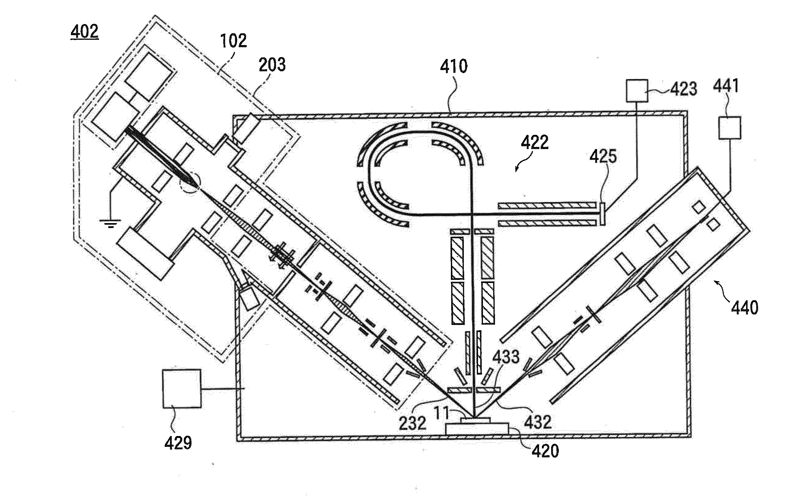
[0161]FIG. 3 illustrates an analysis instrument 302 of the present invention, which is an X-ray photoelectron spectroscopy analysis instrument (XPS) including the above-discussed ion gun 202 so as to perform the X-ray photoelectron spectroscopy using the cluster ion beam.

[0162]This analysis instrument includes an analysis chamber 310, to which a vacuum pump 329 is connected and which is evacuated by the vacuum pump 329; hence, the inside of the analysis chamber 310 is the vacuum environment. Further, the inside of the ion gun 202 is also in a vacuum environment.

[0163]A sample stage portion 320 is disposed inside the analysis chamber 310; and a sample 11 placed on the sample stage portion 320 in the vacuum environment is irradiated with the cluster ion beam232 emitted from the ion gun 202.

[0164]An X-ray emitting device 321 that emits a soft X-ray (such as Al—Kα or Mg—Kα) 331 is disposed at a position facing the sample stage portion 320. A position of the sample 11 irradiated with the...


PUM

PropertyMeasurementUnit
diameteraaaaaaaaaa
outer diameteraaaaaaaaaa

Abstract

Provided are an ion source, an ion gun, and an analysis instrument, which are capable of performing sputtering without damage to a surface of a sample and improving detection sensitivity in mass spectroscopy. In the ion source, an emission opening to which ionization liquid is supplied is disposed in an electric field formed in vacuum environment by an extracting electrode so that super large droplet cluster ions are generated from the emission opening. When the sample is irradiated with a super large droplet cluster ion beam, the sample surface is subjected to sputtering without damage, so as to remove contamination substances or to expose a new surface of the sample. In mass spectroscopy, detection sensitivity is improved.

Description

BACKGROUND OF THE INVENTION[0001]1. Field of the Invention[0002]The present invention relates to a technology for realizing low damage sputtering regardless of materials (such as, an inorganic or organic material) in a surface analysis method, and relates to a technology for realizing improvement of sensitivity by improving secondary ion yield in a secondary ion mass spectroscopy method.[0003]2. Description of the Related Art[0004]An ion source for surface analysis that can perform sputtering without any damage to a target sample has not yet been developed. In the surface analysis, argon ion (Ar+) is the most common ion species for sputtering, but it is known that the occurrence of damage due to the sputtering is high.[0005]In addition, in a secondary ion mass spectroscopy method (SIMS) as one of surface analysis methods, a primary ion beam that has been used so far is a noble gas ion or a metal ion (Cs+, Ar+, Ga+, Au+, or the like). Some of them can be reduced to a small beam in th...

Claims


Application Information

Patent Timeline
Patent Type & Authority Applications(United States)
IPC IPC(8): H01J49/16H01J49/06G01N23/02H01J49/26
CPCH01J49/161G01N23/02H01J49/061H01J49/26G01N23/2258H01J27/26H01J37/08H01J37/252H01J49/0468H01J49/165H01J2237/0812H01J2237/2527H01J2237/3174
Inventor SAKAI, DAISUKESOGOU, MAUOHIRAOKA, KENZO
Owner ULVAC PHI INC
Why Eureka
Try Eureka