
Photovoltaic component with a high conversion efficiency

a photovoltaic component and high conversion efficiency technology, applied in the field of photovoltaic components, can solve the problems of scattered light (scattered by the atmosphere) being lost in these imaging systems, affecting the operation of photovoltaic devices, so as to achieve the wide range of solar spectrum useful to photovoltaic devices, and improve the absorption of the entire spectral band

Active Publication Date: 2015-09-10
CENT NAT DE LA RECHERCHE SCI +2
View PDF3 Cites 7 Cited by
  • Summary
  • Abstract
  • Description
  • Claims
  • Application Information

AI Technical Summary

Benefits of technology

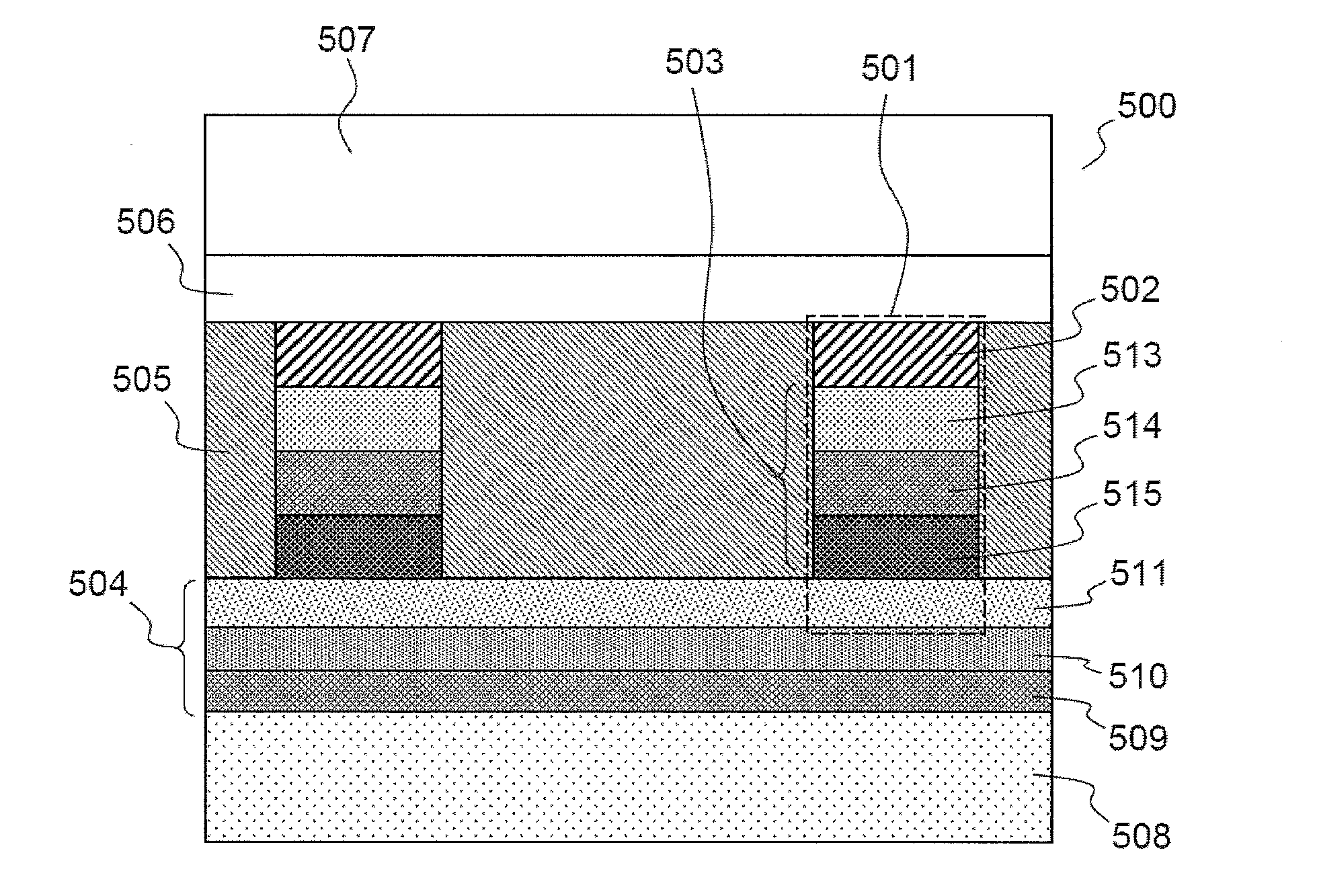
The photovoltaic component described in this patent creates a synergy between two types of concentrators, allowing for optimal absorption of photons. This results in a high conversion efficiency for the component. The spectral conversion layer also allows the component to operate in a single-resonance mode or in a "parallel" mode, widening the range of the solar spectrum used by the component.

Problems solved by technology

This is particularly important for thin-film-based cells, especially chalcopyrite-based cells, because of the limited long-term availability of indium and tellurium.
However, solar light cannot be concentrated on a photovoltaic cell without difficulties.
Scattered light (scattered by the atmosphere) is, for its part, lost in these imaging systems.
In contrast, this system introduces a number of losses, in particular losses due to multiple reflections in the waveguide.

Method used


Image

  • Photovoltaic component with a high conversion efficiency
  • Photovoltaic component with a high conversion efficiency
  • Photovoltaic component with a high conversion efficiency

Examples


Embodiment Construction

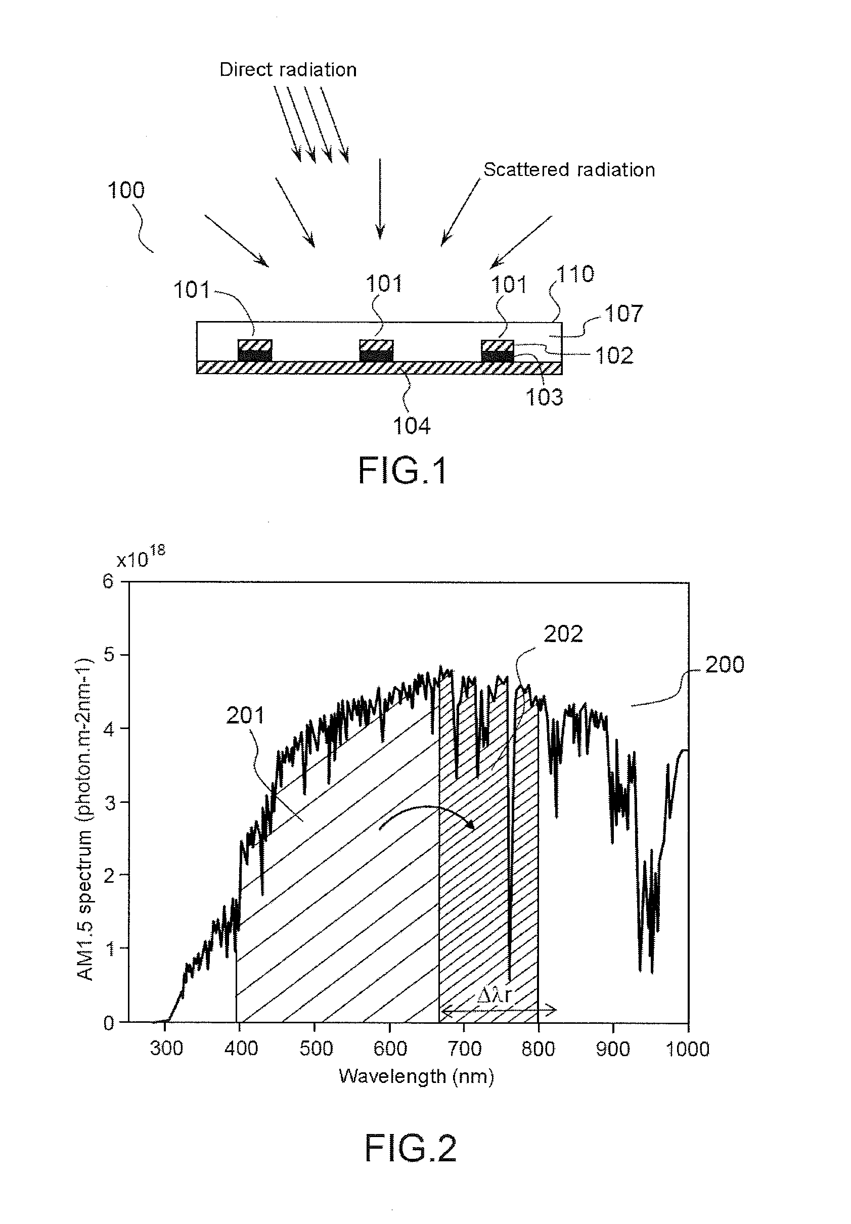
[0041]FIGS. 1 and 2 illustrate, via a simplified schematic and a graph showing spectral absorption / emission bands superposed on the solar spectrum, respectively, the principle of the invention.

[0042]The photovoltaic component 100 schematically shown in FIG. 1 comprises, on its side intended to be exposed to the Sun, a spectral conversion layer 107 for converting all or some of the solar spectrum. The layer 107 comprises a spectral conversion material, for example a luminescent dye, allowing incident solar light to be absorbed and re-emitted isotropically in a spectral band shifted to longer wavelengths, and the width of which is much thinner than that of the solar radiation (typically a few tens to about a hundred nanometres in width). The spectral conversion layer therefore acts as a spectral concentrator. This spectral concentration is illustrated in FIG. 2, the curve 200 of which represents the solar spectrum (AM1.5 solar spectrum in units of numbers of photons / m2 / nm). The hatche...


PUM


Abstract

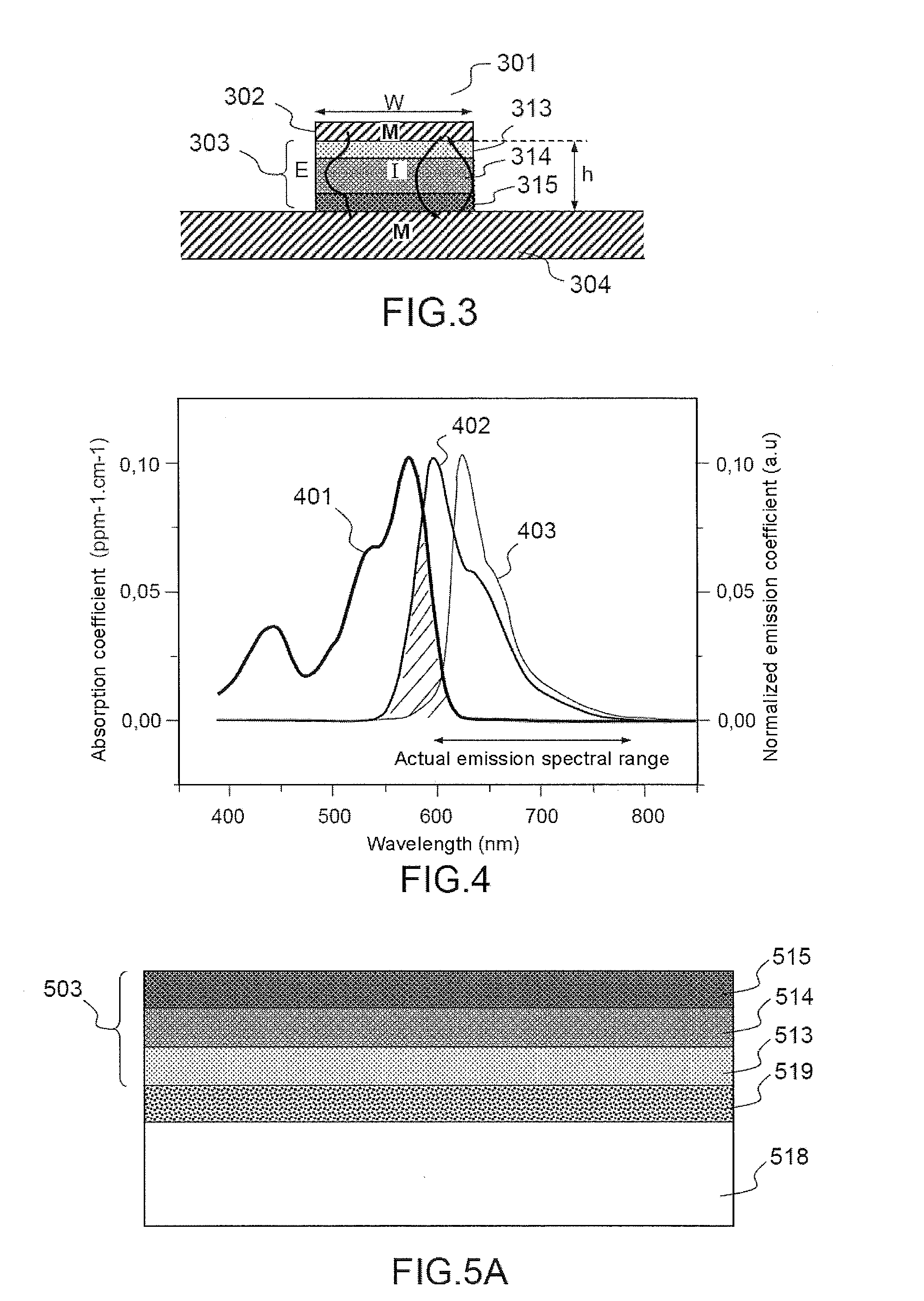
A photovoltaic component that includes at least one first array of photovoltaic nano-cells is disclosed. Each photovoltaic component includes an optical nano-antenna exhibiting an electromagnetic resonance in a first resonant spectral band, at least one lateral dimension of the optical nano-antenna being subwavelength in size, and a spectral conversion layer allowing at least part of the solar spectrum to be converted to said first resonant spectral band.

Description

TECHNICAL FIELD OF THE INVENTION[0001]The present invention relates to a photovoltaic component with an improved conversion efficiency and to its manufacturing process.PRIOR ART[0002]It has been demonstrated that the conversion efficiency of solar cells increases with the intensity of the incident light flux, providing that Joule losses resulting from electrical voltage drops in resistive zones of the cell remain small (see for example M. Paire et al., “Microscale solar cells for high concentration on polycrystalline Cu(In, Ga)Se2 thin films”, Appl. Phys. Letts. 98, 264102 (2011)). It is demonstrated in the article by M. Paire et al. that it is possible with cells of small diameter (from 10 to 500 microns) to achieve high concentration ratios (up to 475), the concentration ratio being defined as the ratio of the flux of photons entering into the cell to the incident flux measured in the far field, while simultaneously limiting resistive losses. This especially allowed conversion eff...

Claims


Application Information

Patent Timeline
IPC IPC(8): H01L31/0232H01L31/0203H01L31/18H01L31/0475
CPCH01L31/02327H01L31/186H01L31/0203H01L31/0475H01L27/142H01L31/035209H01L31/055H01L31/108Y02E10/52
Inventor PELOUARD, JEAN-LUCGUILLEMOLES, JEAN-FRANCOISPROISE, FLORIANPAIRE, MYRIAMLINCOT, DANIEL
Owner CENT NAT DE LA RECHERCHE SCI
Learn More