Tapered scaffolds

Inactive Publication Date: 2015-09-24
ABBOTT CARDIOVASCULAR
View PDF14 Cites 41 Cited by
  • Summary
  • Abstract
  • Description
  • Claims
  • Application Information

AI Technical Summary

Benefits of technology

[0019](1) The prescribed taper precludes a subtractive method such as extrusion followed by laser machining. Extrusion is preferred for constant cross-section scaffolds or stents. Laser machining is also preferred for removing material from a constant cross-section tube due to the challenges with maintaining a precision focal point for the laser if the tubing is not rotated concentrically in the cutting plane. The scaffolds described here are not constant cross-section. The scaffolds disclosed are tapered.
[0020](2) Maintaining a constant aspect ratio of the strut cross-section is preferred to ensure the crimping behavior of the scaffold is consistent along the length. Therefore, if a strut width i

Problems solved by technology

(1) The prescribed taper precludes a subtractive method such as extrusion followed by laser machining. Extrusion is preferred for constant cross-section scaffolds or stents. Laser machining is also preferred for removing material from a constant cross-section tube due to the challenges with maintaining a precision focal point for the laser if the tubing is not rotated concentrically in the cutting plane. The scaffolds described here are not constant cross-section. The scaffolds disclosed are tapered.
(2) Maintaining a constant aspect ratio of the strut cross-section is preferred to ensure the crimping behavior of the scaffold is consistent along the length. Therefore, if a strut width is chan

Method used


Image

  • Tapered scaffolds
  • Tapered scaffolds
  • Tapered scaffolds

Examples


example a

[0141]Arteriovenous fistulae are becoming a primary method of vascular access for hemodialysis patients. Still, failure rate is high often due to non-maturation of fistula due to complex hemodynamic factors within vessels. By implanting a prosthesis that is capable of functioning as a coupler between the artery and vein, one can better control the velocity profile within / between the vessels, thereby reducing areas of low / oscillatory shear stress, minimizing neointimal growth, and reducing the prevalence of stenosis within the fistulae space.

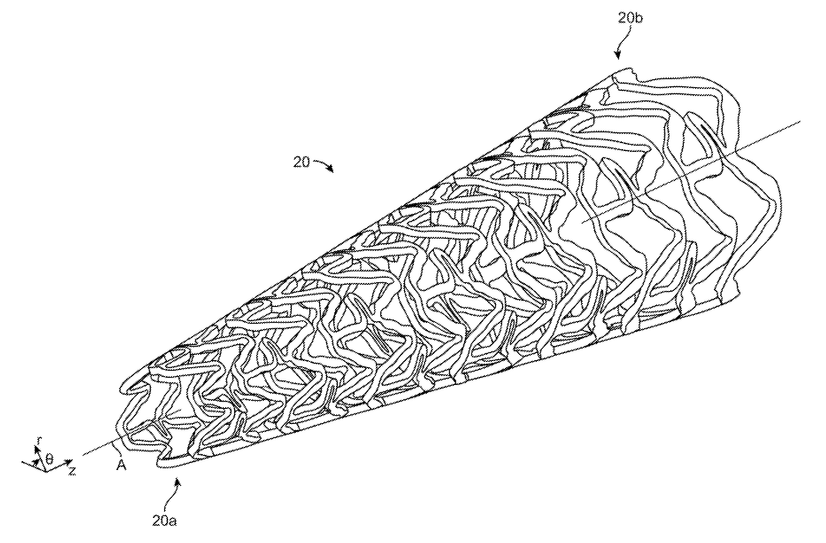
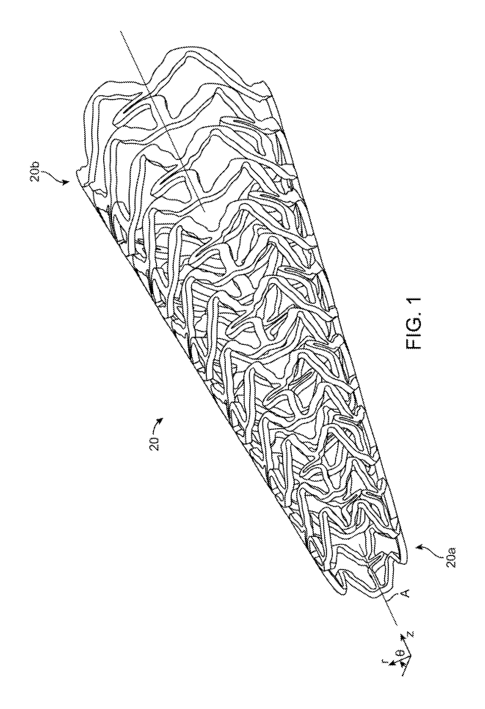
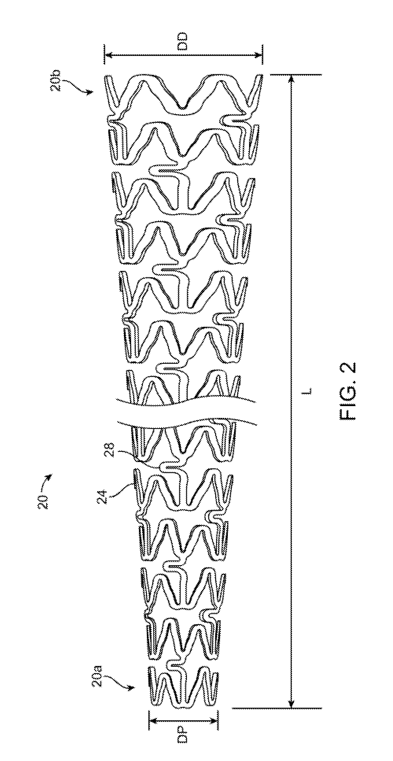
[0142]According to one embodiment, the scaffold 20 is used as an intravascular support for supporting a venous portion of an arteriovenous fistula (AVF). According to this application the proximal end 20a would be located nearest the fistula and the distal end 20b would be located furthest the fistula. As the vein matures the size increases. The taper angle for the frustum scaffold may vary from about 5 to 8 degrees up to 10 to 12 degrees. Genera...

example b

[0170]This embodiment pertains to the scaffolds 40 or 60 (see FIGS. 5A-5C). According to this example, the scaffold when implanted can exhibit low mechanical trauma; hence, it can reduce if not eliminate any hyperplastic cellular response. Hyperplastic cellular response is known to cause soft-tissue stenosis or obstruction.

[0171]Referring to TABLE B, below, the overall size, i.e., diameter ranges and lengths, accommodates the various diameters encountered for longer vasculature that taper with length. These geometries are far more practical utilizing AM methods and in several of the embodiments outlined below it will be understood that traditional manufacturing methods for scaffold made from a tube cannot be used, or are simply impractical and of little value or utility in achieving stated the above-stated goals for tapered scaffolds.

TABLE BEmbodiment 2:Flared End polymeric scaffold, absorbed or durable polymer.Properties:Thickness range, t = 75-150 μm and constant for all struts an...

example c

[0172]This embodiment pertains to scaffolds 70, 80 or 90. The scaffold is an AV graft for dialysis access. The ranges given in TABLE C reflect the expected range of vein and artery sizes. These geometries are far more practical utilizing AM methods and in several of the embodiments outlined below it will be understood that traditional manufacturing methods for scaffold made from a tube cannot be used, or are simply impractical and of little value or utility in achieving stated the above-stated goals for tapered scaffolds.

TABLE CEmbodiment 3:Polymeric scaffold, Absorbable or durable, with a porous jacketProperties:Scaffold or stent properties the same as embodiments 1 or 2.A durable or absorbable polymer jacket with axially varying porosity willbe applied over the scaffold.Jacket / sheath porosity Pgraft(z) will be designed at distal 2-5 mm at avalue range of (40-80 μm pore size) for Section B, proximal 2-5 mm at avalue range of (40-80 μm pore size) for Section A; constant overrest of ...


PUM

PropertyMeasurementUnit
Fractionaaaaaaaaaa
Pressureaaaaaaaaaa
Pressureaaaaaaaaaa

Abstract

A stent or scaffold has a tapered end or ends. The scaffold is made using an additive manufacturing technique such as stereolithography (SLA). The scaffold may take the shape of a frustum, or a scaffold having one or both of its ends flared. The scaffold has varying mechanical properties over its length, such as a varying ring stiffness, porosity or elasticity modulus. In one embodiment the strut and link widths change linearly from the distal to proximal ends.

Description

PRIORITY STATEMENT[0001]This application claims priority to U.S. Provisional Application No. 61 / 955,127 filed Mar. 18, 2014, the entire contents of which are hereby incorporated by reference.BACKGROUND OF THE INVENTION[0002]1. Field of the Invention[0003]This invention relates to additive manufacturing methods applied to bioresorbable implantable medical devices.[0004]2. Description of the State of the Art[0005]This invention relates generally to medical devices and methods of manufacturing medical device that are in whole or in part biodegradable. In particular, the devices include implantable medical devices for treating bodily lumens such as blood vessels. The devices include radially expandable endoprostheses that are adapted to be implanted in a bodily lumen. The devices also include devices that are generally adapted to delivery of drugs of an arbitrary shape such as particles.[0006]An “endoprosthesis” corresponds to an artificial device that is placed inside the body. A “lume...

Claims


Application Information

Patent Timeline
IPC IPC(8): A61F2/89A61F2/958A61L31/04A61F2/844
CPCA61F2/89A61F2/844A61F2/958A61L31/041A61F2210/0004A61F2250/0067A61F2250/0018A61F2250/0023A61F2250/0036A61F2250/0039A61F2230/0067A61F2/915A61F2002/072A61F2002/91566A61F2230/0078C08L67/04
Inventor HOSSAINY, SYEDVAN SCIVER, JASONABUNASSAR, CHAD
Owner ABBOTT CARDIOVASCULAR
Why Eureka
Try Eureka