

Ultrasensitive Ion Detector Using Carbon Nanotubes or Graphene
a technology of carbon nanotubes and ion detectors, applied in the direction of optical radiation measurement, instruments, particle separator tubes details, etc., can solve the problems of low bias voltage operation and inability to direct sensing ions with high sensitivity using carbon nanomaterials
- Summary
- Abstract
- Description
- Claims
- Application Information
AI Technical Summary
Benefits of technology
Problems solved by technology
Method used
Image

Examples
example 1
Fabrication of a Microscale Miniaturized Ion Detector using Carbon-Based Nanomaterials
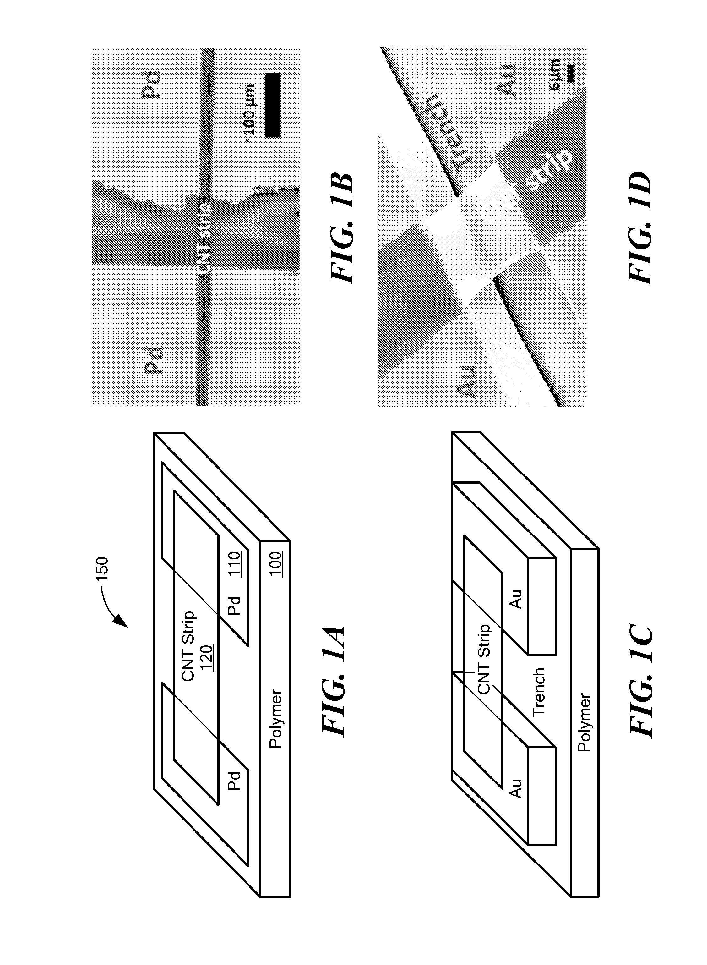
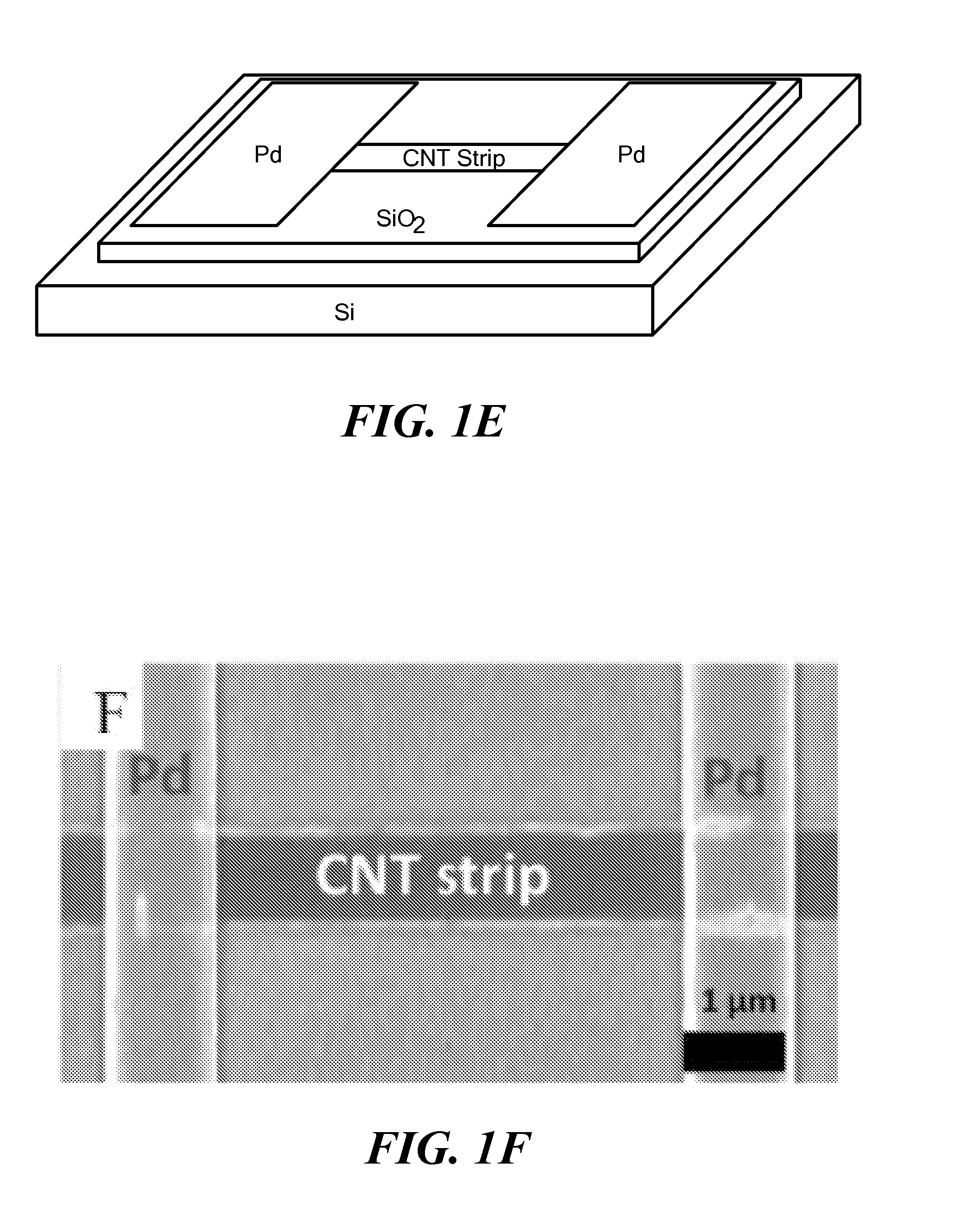
[0078]A Si / SiO2 substrate (SiO2 layered on to Si) of about 400 nm thickness was pretreated with inductively coupled plasma using a mixed gas flow of O2 (20 sccm), SF6 (20 sccm), and Ar (5 sccm). A microscale SWCNT film was assembled on the SiO2 / Si substrate by dip-coating the plasma treated substrate into a suspension of SWCNT in deionized water, and removing the substrate from the suspension at a constant speed (0.05 mm / min) The SWCNT strip was composed of both metallic and semi-conductive SWCNTs. A layer of photoresist (S1818, MicroChem Corp., Newton, Mass.) was spin coated on top of the SWCNT and patterned to generate strips of exposed SWCNT, each strip 20 μm in width. O2 plasma was used to etch the strips of exposed SWCNT film, and after removing the photoresist, an array of SWCNT strips was obtained. An SWCNT strip was transferred using a wet-contact print method to a receiving substrate (SU-8...
example 2
Fabrication of a Nanoscale Miniaturized Ion Detector using Carbon Based Nanomaterials
[0080]A nanoscale miniaturized ion detector having an SWCNT strip of 200 nm width is fabricated using the same general method as described above, except that the SWCNT strip is formed by the method of template-guided fluidic assembly (Kim et al., 2009). A similar device, but having a single SWCNT spanning two contact pads, is achieved by the method of guided growth (Kong et al., 1998), where metallic catalyst islands are scattered on a Si substrate, and individual SWCNT are grown bridging two isolated metallic islands through a chemical vapor deposition process forming a measurable device. Another method for obtaining a single SWCNT device is deposition after growth, where a Si substrate coated with a self-assembled monolayer terminated with —CH3 groups is soaked in SWCNT / N,N-dimethylformamide solution (0.1 mg / ml) for 10 min, immediately followed by methanol rinsing and blow-drying with nitrogen (Li...
example 3
Ion Detection using Devices Having Carbon Based Nanomaterials (CNM)
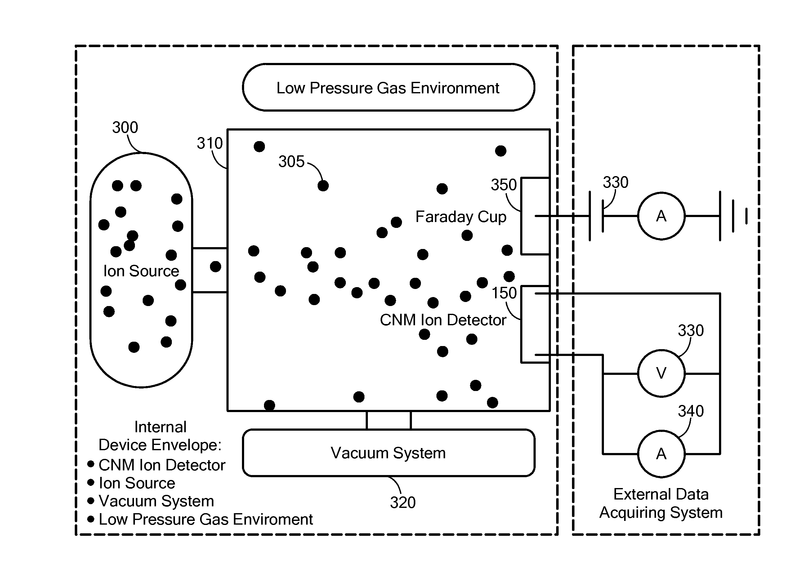
[0081]Ion detection was performed in a well-grounded and shielded chamber at room temperature (294 K) and with controlled pressure. Positive ions were generated by a hot-filament ionization generator and air was used as the gas source. Gas molecules were bombarded with accelerated electrons to generate positive ions. The electrons and negatively charged particles were terminated by applying a grid with high positive potential, and only positive ions were released from the ion generator. Pure N2 and Ar were also used with similar results. The number of ions generated is proportional to the number of gas molecules, and therefore to the pressure within the ion generator. The higher the pressure the larger the number of positive ions generated.
[0082]A pump was used to gradually decrease the pressure within the shielded chamber, and the ion source was turned on and off several times to supply fresh ions. See solid squares...
PUM
 Abstract
Description
Claims
Application Information