
Multi-well plate

a multi-well plate and plate body technology, applied in the field of multi-well plate, can solve the problems that the animal studies of model systems such as mice and rats do not accurately represent the more complex human physiological environment, and achieve the effects of stimulating the production of extracellular matrix (ecm), high consistency and reproducibility, and facilitating the growth of three-dimensional (3d) cell cultures

Inactive Publication Date: 2015-10-08
THE ELECTROSPINNING CO LTD
View PDF5 Cites 8 Cited by
  • Summary
  • Abstract
  • Description
  • Claims
  • Application Information

AI Technical Summary

Benefits of technology

The present invention provides a multi-well plate that allows for the growth of three-dimensional cell cultures with high consistency and reproducibility between wells and plates. The plate supports the growth of a variety of cell types and is more accurate in drug discovery compared to traditional 2D cell cultures. The scaffold layer in each well is a porous network of polymer nanofibers that ensures consistent and reproducible cell growth and assay measurement. The use of a 3D network of nanofibers as the scaffold layer provides greater consistency and reproducibility compared to alternative scaffold materials. The scaffolds are produced using electrospinning and have a consistent pore size and low relative standard deviation from the mean. This makes them ideal for facilitating the growth of three-dimensional cell cultures and tissue engineering applications.

Problems solved by technology

Furthermore, animal studies on model systems such as mice and rats do not accurately represent the more complex human physiological environment for which the drug is ultimately intended.

Method used


Image

  • Multi-well plate
  • Multi-well plate
  • Multi-well plate

Examples


example 1

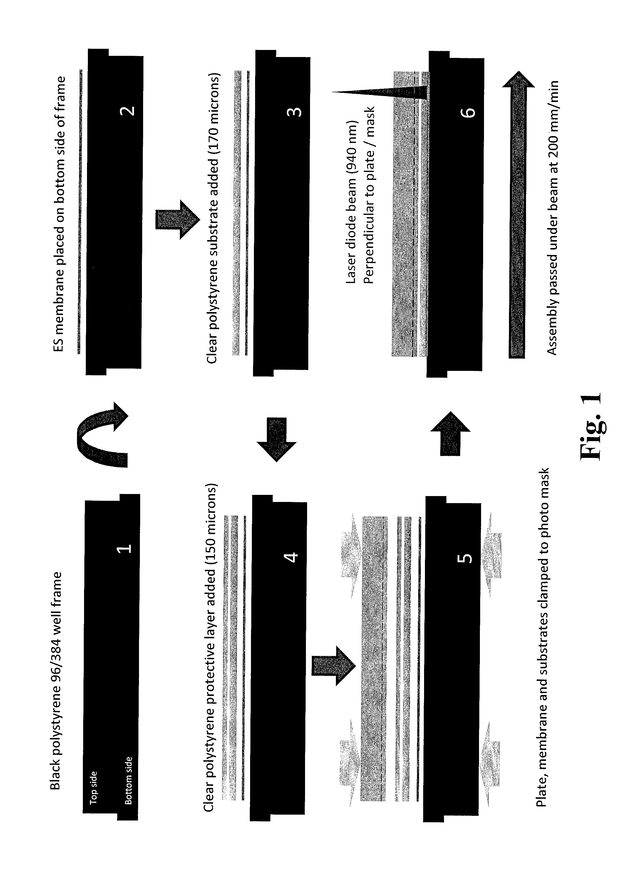
Scaffold Fabrication and Preparation of Multi-Well Plate

1. Scaffold Fabrication by Electrospinning

[0289]A solution was prepared by dissolving 3.0 grams of polymer, poly(L-lactide), (poly[(3S-cis)-3,6-dimethyl-1,4-dioxane-2,5-dione]), having an Inherent Viscosity Midpoint of 1.8 dl / g, in 27.0 grams of the solvent, 1,1,1,3,3,3-Hexafluoroisopropanol (HFIP), with continuous stirring at room temperature until a homogeneous solution of the required concentration, 10 wt %, was obtained. The polymer solution was loaded into a plastic syringe connected to a metal capillary (21 gauge) via PTFE tubing. The metal capillary was connected to the positive terminal of a high voltage, DC power supply, at a fixed distance of 300 mm from an earthed metallic collection device (covered in an Aluminium foil / silicone coated release paper substrate) onto which the fibres were deposited. The collection device was a rotating drum to ensure uniform deposition of the material. Fibres were produced by passing t...

example 2

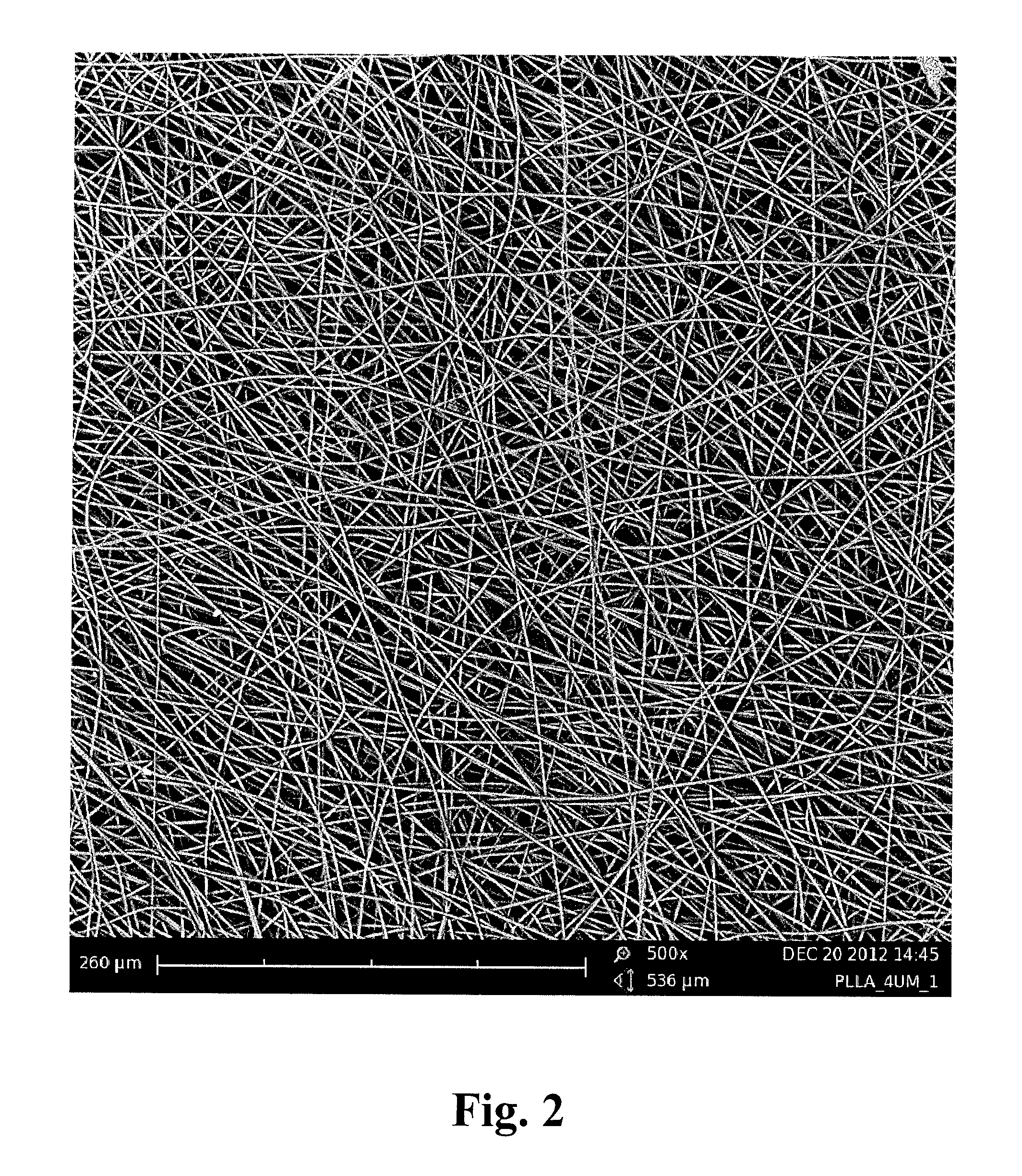
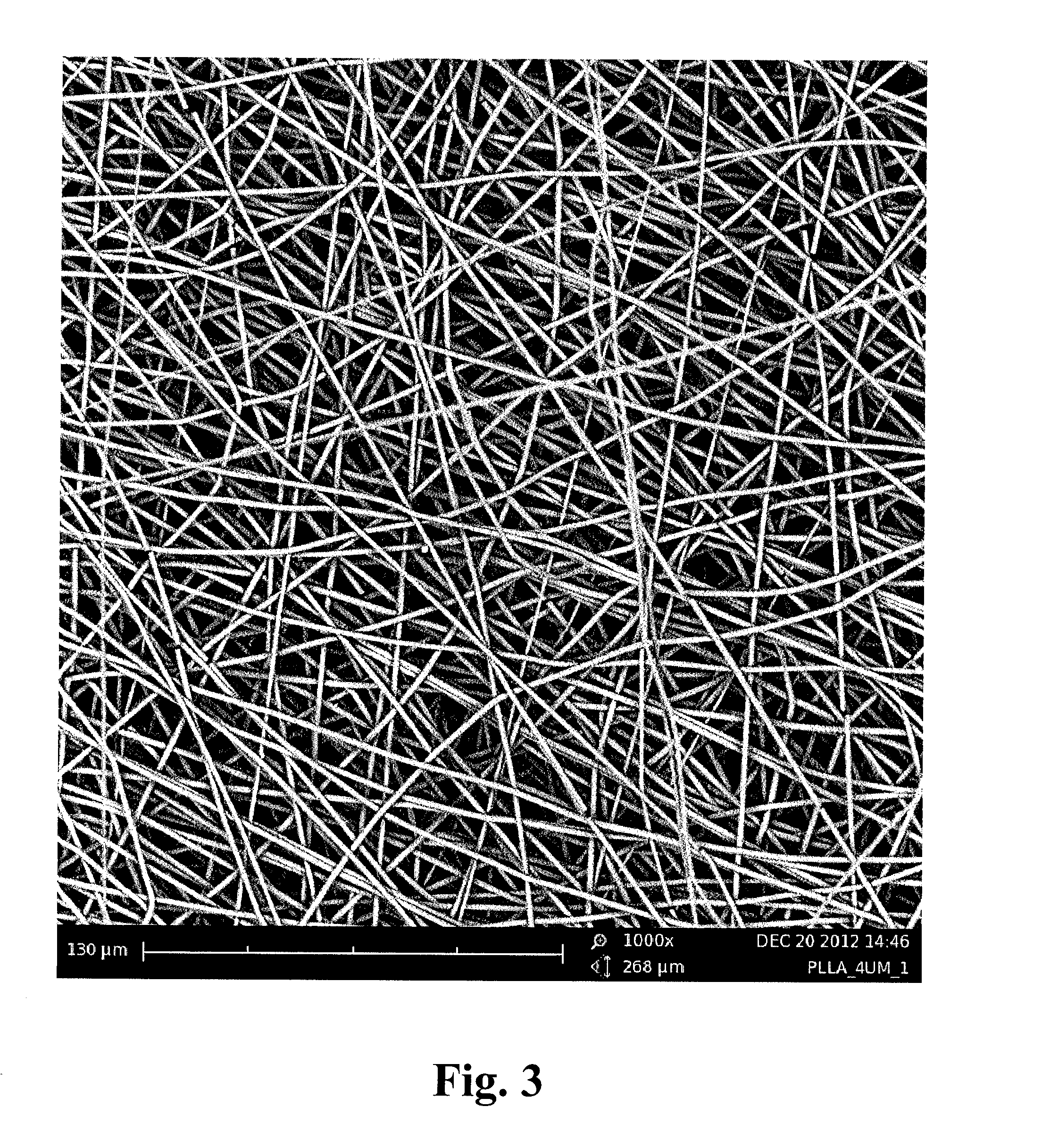
Measurement of Fibre Diameter and Diameter Distribution

[0300]Scaffolds were fabricated by electrospinning using the method described in Example 1. The electrospun samples were imaged using a Phenom G2 pro scanning electron microscope, which allows for automatic fibre diameter measurements by the Fibremetric Software Application from PhenomWorld. Fibre samples were mounted onto conductive adhesive tabs and loaded into a charge reduction sample holder, which was subsequently inserted into the scanning electron microscope (SEM). SEM images of the fibres were obtained, examples of which are shown in FIG. 2 (500× magnification image), FIG. 3 (1000× magnification image) and FIG. 4 (2000× magnification image). To obtain a statistically sound measurement of the fibre diameter distribution, the diameters of 100 fibres were measured using an image at 1000-2000× magnification. In some instances, the software recognises two fibres which cross or stick together as one; these data points were del...

example 3

Comparative Testing of Scaffolds of 2 μm Fibre Diameter and 4 μm Fibre Diameter, Each in Two (2) Scaffold Thicknesses

[0317]Production of Scaffolds with 2 μm Fibre Diameter

[0318]Scaffold membranes having thicknesses of 50 μm and 100 μm, and containing poly(L-lactide) fibres with a mean diameter of 2 μm, were produced by the electro spinning method described in Example 1 above.

Production of Scaffolds with 4 μm Fibre Diameter

[0319]Scaffold membranes having thicknesses of 50 μm and 100 and containing poly(L-lactide) fibres with a mean diameter of 4 μm, were produced by the following method:

[0320]A solution was prepared by dissolving 4.5 grams of polymer, poly(L-lactide), (poly[(3S-cis)-3,6-dimethyl-1,4-dioxane-2,5-dione]), having an Inherent Viscosity Midpoint of 1.8 dl / g, in 25.5 grams of the solvent, 1,1,1,3,3,3-Hexafluoroisopropanol (HFIP), with continuous stirring at room temperature until a homogeneous solution of the required concentration, 15 wt %, was obtained. The polymer solut...


PUM

PropertyMeasurementUnit
diameteraaaaaaaaaa
diameteraaaaaaaaaa
widthaaaaaaaaaa

Abstract

The invention provides a multi-well plate, comprising: a plate base, which defines the bottom of a plurality of sample wells; a scaffold layer disposed on the plate base, which scaffold layer provides a porous three-dimensional network of polymer nanofibres in each of said sample wells; and a plate frame, which defines the side walls of said sample wells; wherein the plate frame is bonded to the plate base through the scaffold layer. The invention further provides a process for producing the multi-well assay plate. Further provided is a scaffold which comprises a porous three dimensional network of electrospun polymer nanofibres, wherein the mean diameter of the polymer nanofibres is from 500 nm to 10 μm. A process for producing the scaffold is also provided, as are various uses of the multi-well plate and the scaffold in drug screening, regenerative medicine and tissue engineering.

Description

FIELD OF THE INVENTION[0001]The present invention relates to a multi-well assay plate which is suitable for use in cell-based assays, and to a process for producing a multi-well assay plate.BACKGROUND TO THE INVENTION[0002]Multi-well assay plates (also known as multi-well plates, microplates or microtiter plates) are known in the art and have a broad application in the life sciences, including in cell biology, microbiology, biophysics, pharmacology, toxicology and immunology, as well as other scientific fields. Typically, samples and reagents are stored, processed and / or analysed in multi-well plates.[0003]Multi-well plates can take a variety of forms, shapes and sizes, and are particularly well suited for screening a number of samples at the same time. Standard sizes have appeared with the development of laboratory equipment that has been specifically designed for the multi-well plate format, including plate-readers, plate shakers, automated high throughput screening equipment, and...

Claims


Application Information

Patent Timeline
Patent Type & Authority Applications(United States)
IPC IPC(8): B01L3/00C12M1/12C12M3/00C12M1/32
CPCY10T156/10B01L3/5085C12M23/12C12M25/14B01L2300/0896B01L2200/12B01L2300/12B01L2300/06B01L2300/0829C12M21/08B01L3/50255B01L2300/0681
Inventor MCKEAN, ROBERT JAMES
Owner THE ELECTROSPINNING CO LTD
Learn More