Coating system, method of coating a substrate, and gas turbine component

a coating system and substrate technology, applied in the direction of superimposed coating process, solid-state diffusion coating, machines/engines, etc., can solve the problems of gas turbine components subject to oxidation and/or corrosion

Inactive Publication Date: 2015-10-22
SIEMENS AG
View PDF4 Cites 6 Cited by
  • Summary
  • Abstract
  • Description
  • Claims
  • Application Information

AI Technical Summary

Benefits of technology

[0005]It is an objective of the present invention to provide an improved coating system and an improved method of coating a substrate. It is a further objective of the present invention to provide a gas turbine component with an advantageous coating system.
[0010]In the inventive coating system the inner aluminide layer serves as a final line of protection for the underlying superalloy substrate. The intermediate layer, which has a high chromium content, serves as protective layer against type II corrosion, and the outer coating layer, which has a high aluminium content, serves as a protection layer to protect against type I corrosion. In other words, the inventive coating system includes a specialized layer to protect against type I corrosion and a specialized layer to protect against type II corrosion. Therefore, the component is well protected against corrosion and / or oxidation over the full range of temperatures from 670° C. to 950° C.
[0013]According to a further development of the inventive coating system the intermediate coating layer comprises up to 1% by weight yttrium (Y) and / or up to 2% by weight silicon (Si) and / or up to 1% by weight hafnium (Hf). Additionally or alternatively, the outer coating layer comprises up to 1% by weight yttrium and / or up to 2% by weight silicon and / or up to 1% by weight hafnium. Silicon, hafnium and yttrium contribute to stabilizing the oxide formed during a corrosive attack and therefore slow down the attack further.
[0033]Likewise, it is advantageous if the slurry applied onto the inner coating layer and / or the slurry applied onto the intermediate coating layer is / are diffusion heat treated for 2 to 4 hours.

Problems solved by technology

Due to the harsh environment generated by hot and corrosive combustion gases used as working fluid of gas turbines the components of gas turbines are subject to oxidation and / or corrosion.

Method used


Image

  • Coating system, method of coating a substrate, and gas turbine component
  • Coating system, method of coating a substrate, and gas turbine component
  • Coating system, method of coating a substrate, and gas turbine component

Examples


Embodiment Construction

[0044]Typical gas turbine components to which the inventive coating system may be applied are turbine vanes and blades in particular those surfaces of turbine vanes and blades which come into contact with the hot and corrosive working fluid of a gas turbine.

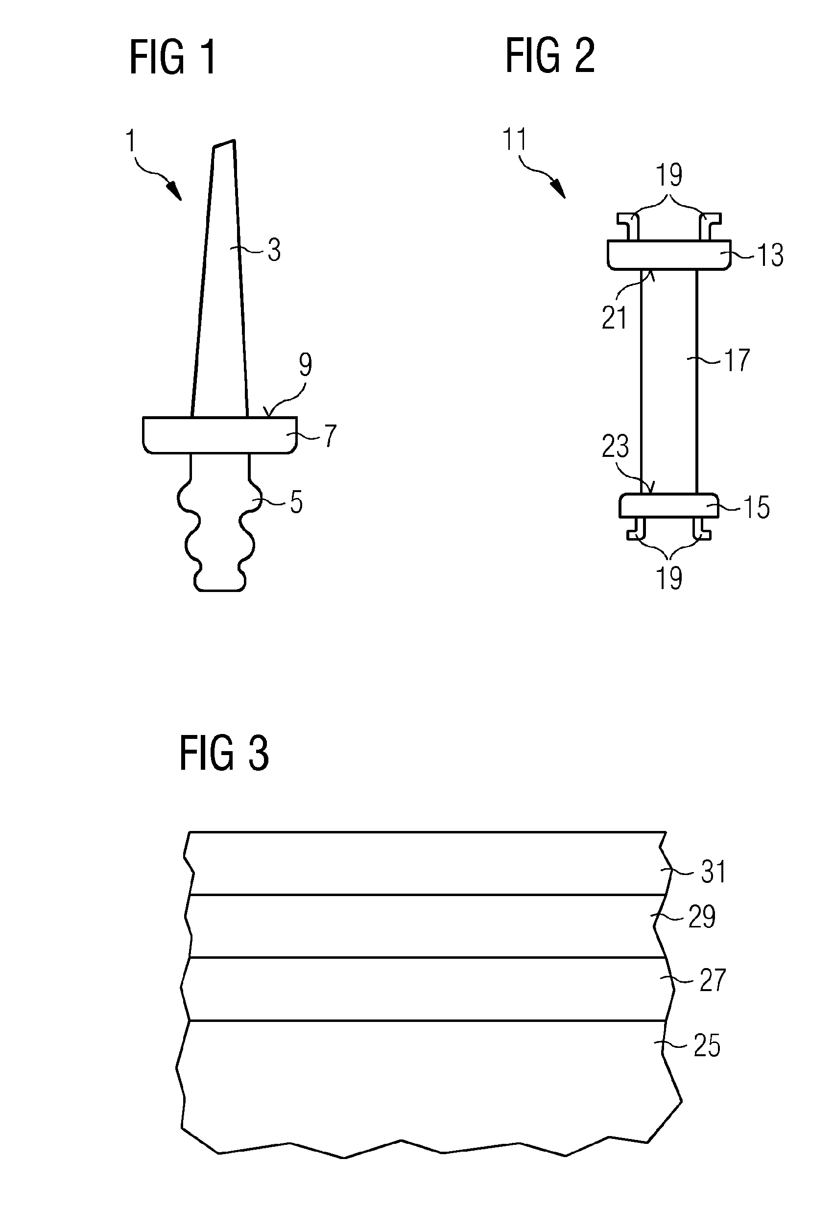
[0045]A typical rotor blade is schematically shown in FIG. 1, whereas typical stator vane is schematically shown in FIG. 2.

[0046]A typical rotor gas turbine rotor blade comprises an airfoil section 3, a root section 5 and a platform 7 located between the airfoil section 3 and the root section 5. The rotor blade is fixed to a rotor shaft (not shown) by means of the root section 5 which has a special shape that is adapted to the shape of a notch in the rotor shaft. In the present illustration, a so-called dovetail root is shown.

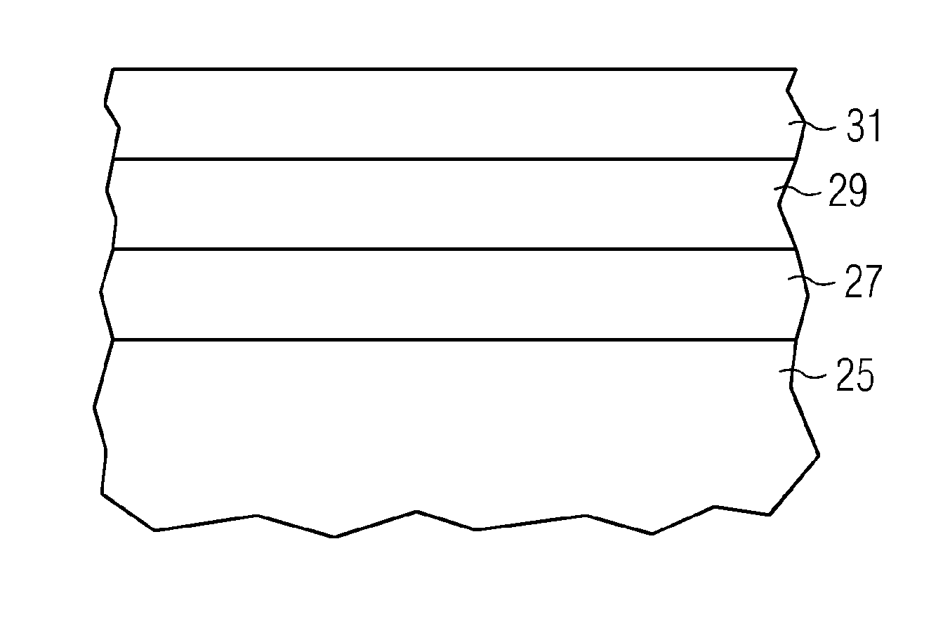
[0047]Those parts of the turbine blade coming into contact with hot and corrosive combustion gases, which form the working medium of a gas turbine, are the surface of the airfoil section 3 and the radial out...


PUM

PropertyMeasurementUnit
temperatureaaaaaaaaaa
temperaturesaaaaaaaaaa

Abstract

A coating system for a superalloy substrate is provided. The coating system has an inner coating layer, an intermediate coating layer and an outer coating layer. The inner coating layer is an aluminide layer, the intermediate coating layer is a diffusion layer including Cr, Al, Ni and Co, where the Cr-content is between 15% by weight and 30% by weight, and the outer coating layer is a Cr-free diffusion layer including Al and Ni, where the Al-content is between 15% by weight and 30% by weight.

Description

CROSS REFERENCE TO RELATED APPLICATIONS[0001]This application is the US National Stage of International Application No. PCT / EP2013 / 073523 filed Nov. 11, 2013, and claims the benefit thereof. The International Application claims the benefit of European Application No. EP12196541 filed Dec. 11, 2012. All of the applications are incorporated by reference herein in their entirety.FIELD OF INVENTION[0002]The present invention relates to a coating system for a superalloy substrate, in particular a nickel-based, cobalt-based or iron-based substrate as well as to a method of coating a superalloy substrate. In addition, the invention relates to a gas turbine component, in particular to a nickel-based, cobalt-based or iron-based superalloy turbine component, with a coating system.BACKGROUND OF INVENTION[0003]Due to the harsh environment generated by hot and corrosive combustion gases used as working fluid of gas turbines the components of gas turbines are subject to oxidation and / or corrosion...

Claims


Application Information

Patent Timeline
Patent Type & Authority Applications(United States)
IPC IPC(8): F01D25/00B05D3/02C23C16/02B32B15/01C23C16/06
CPCF01D25/005B32B15/017B05D3/0254C23C16/0272C23C16/06C23C10/02C23C10/52C23C10/54C23C10/56C23C10/60C23C28/02C23C28/021C23C28/022C23C28/023
Inventor WALKER, PAUL MATHEW
Owner SIEMENS AG
Why Eureka
Try Eureka