Radiation detection device and method for manufacturing the same

Inactive Publication Date: 2015-11-05
TORAY IND INC
View PDF4 Cites 8 Cited by
  • Summary
  • Abstract
  • Description
  • Claims
  • Application Information

AI Technical Summary

Benefits of technology

The present invention provides technology to process a barrier rib with high accuracy in a large area and reduce its width, as well as prevent visible light emitted by a phosphor from leaking outside the barrier rib. This results in a radiation detection device with high luminous efficiency and realizes clear image quality. The invention allows for the formation of large-size and clear images in photographing.

Problems solved by technology

However, the FPD has a problem such as a low S / N ratio.
However, in the method of etching a silicon wafer, the size of a formable scintillator panel is limited by the size of the silicon wafer, and a scintillator panel having a large size of 500 mm square could not be obtained.
However, it is difficult to produce the scintillator panel in view of accuracy, and a large-area scintillator panel was scarcely produced.
In the multi-layer screen printing method using a glass paste, it is difficult to process with high accuracy due to a dimensional variation of a screen printing sheet, or the like.
However, if the width of the barrier rib increases, a space between barrier ribs becomes relatively small, so that a volume available for filling an X-ray phosphor decreases, and the filling amount is not uniform.
Therefore, a scintillator panel obtained in this method has a disadvantage such as a decrease in luminescence or occurrence of luminous unevenness because of too small amount of an X-ray phosphor.
This disadvantage of flexibility is an obstacle to formation of clear images in photographing at a low dose.

Method used


Image

  • Radiation detection device and method for manufacturing the same
  • Radiation detection device and method for manufacturing the same

Examples


example 1

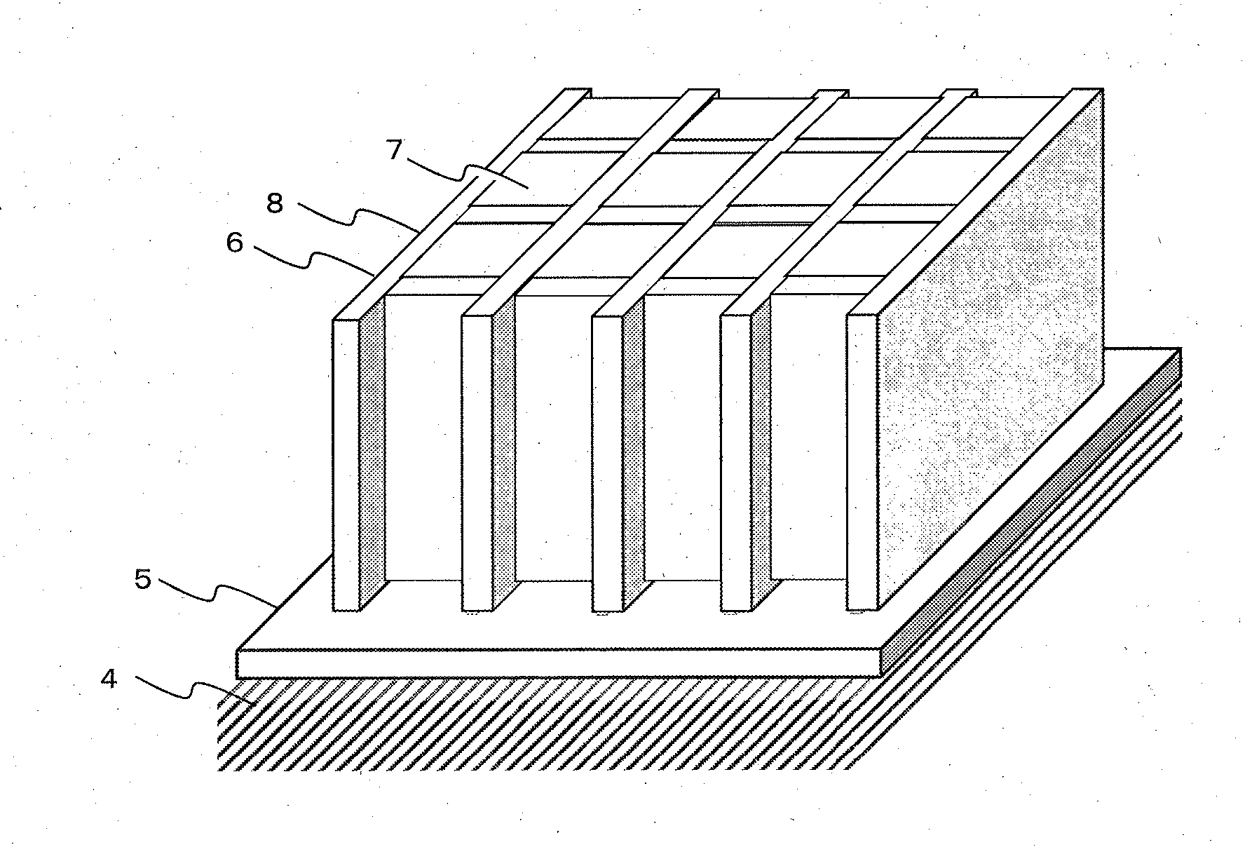
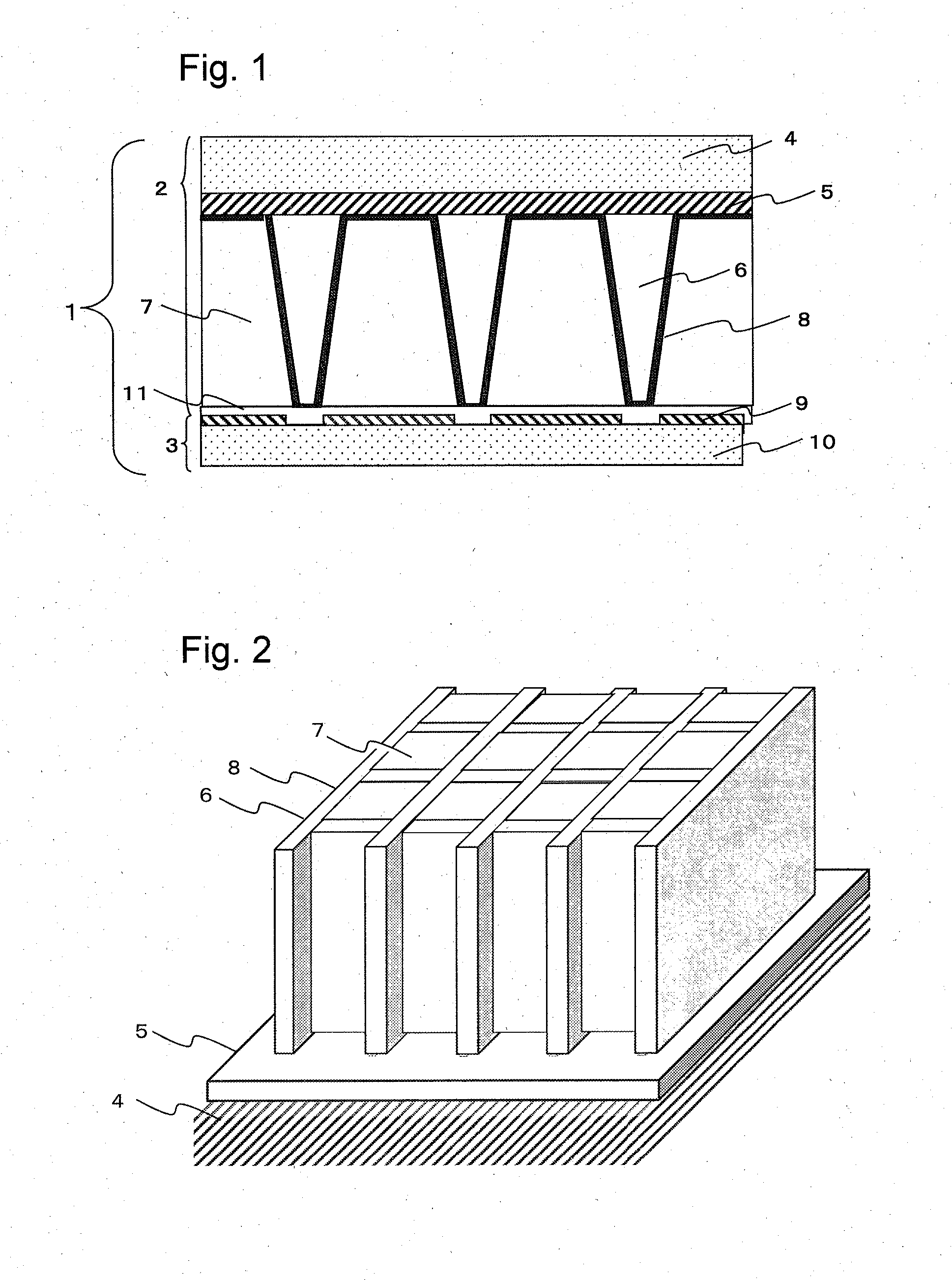
[0102]On a glass substrate having a size measuring 500 mm×500 mm (“OA-10”, manufactured by Nippon Electric Glass Co., Ltd.), a photosensitive paste for barrier rib was applied by a die coater so as to obtain a dry thickness of 500 μm, followed by drying to form a photosensitive paste for barrier rib coating film. Next, the photosensitive paste coating film for barrier rib was exposed at an exposure dose of 700 mJ / cm2 by an ultra-high pressure mercury lamp through a photomask having an opening corresponding to a desired barrier rib pattern (chrome mask having a grid-like opening having a pitch of 125 μm and a line width of 10 μm). The exposed photosensitive paste coating film for barrier rib was developed in an aqueous 0.5 mass % ethanolamine solution to remove the unexposed area, thus forming a grid-like photosensitive paste coating film pattern. Further, the photosensitive paste coating film pattern was fired in air at 585° C. for 15 minutes to produce a substrate with a grid-like ...

example 2

[0107]In the same manner as in Example 1, a substrate, on which a grid-like barrier rib is provided, was produced. Thereafter, an aluminum film, namely, a reflecting film was formed on a barrier rib surface and a substrate surface of the place where no barrier rib is formed by a batch type sputtering system (“SV-9045”, manufactured by ULVAC, Inc.). The thickness of the thus formed aluminum film at the barrier rib top was 300 nm, the thickness of the aluminum film of the barrier rib side was 100 nm, and the thickness of the aluminum film on the substrate was 100 nm.

[0108]Next, a gadolinium oxysulfide powder having a particle diameter of 5 μm and a refractive index of 2.2, as a phosphor, was mixed with ethyl cellulose having a refractive index of 1.5, and then a space divided by the barrier rib was filled with the mixture to produce a scintillator panel in which a volume fraction of a phosphor in the cell is 90%. Using the thus obtained scintillator panel, a radiation detection device...

example 3

[0109]In the same manner as in Example 1, except that the glass substrate of Example 1 was replaced by a tungsten substrate having a size measuring 300×300 mm (manufactured by Applied Materials, Inc.), a radiation detection device was produced and evaluated. As a result, noise decreased since X-ray transmitted through the radiation detection device was absorbed to the tungsten substrate, and thus luminance was 110 and sharpness was 165, and the both exhibited satisfactory value.


PUM


Abstract

The present invention provides a radiation detection device which is provided with a narrow-width barrier rib with high accuracy in a large area, and also has high luminous efficiency and realizes clear image quality. The present invention provides a radiation detection device, including a substrate, on which a barrier rib is provided, and a light detector, which face each other, wherein cells divided by the barrier rib are formed in a space between the substrate and the light detector, the cells are filled with a phosphor, a light detection pixel is provided on a surface of the light detector which is not in contact with the barrier rib, and an adhesive layer is formed between the barrier rib and the phosphor, and the light detector.

Description

CROSS REFERENCE TO RELATED APPLICATIONS[0001]This is the U.S. National Phase application of PCT / JP2013 / 078560, filed Oct. 22, 2013, which claims priority to Japanese Patent Application No. 2012-241512, filed Nov. 1, 2012, the disclosures of these applications being incorporated herein by reference to their entireties for all purposes.TECHNICAL FIELD OF THE INVENTION[0002]The present invention relates to a radiation detection device which is used for a medical diagnostic apparatus, a nondestructive inspection instrument, and the like.BACKGROUND OF THE INVENTION[0003]Heretofore, X-ray images using films have widely been used in medical settings. However, the X-ray image using a film provides analog image information, and thus digital radiation detection devices such as computed radiography (CR) and flat panel radiation detection devices (flat panel detectors: FPDs) have recently been developed.[0004]In a flat panel X-ray detector (FPD), a scintillator panel is used for converting radi...

Claims


Application Information

Patent Timeline
IPC IPC(8): G01T1/20H01L27/146H01L31/0232
CPCG01T1/2002H01L31/02322H01L27/14663H01L27/14623H01L27/14685G01T1/20183G01T1/2019
Inventor OKAMURA, MASAKIIGUCHI, YUICHIROMURAI, TAKAHIRO
Owner TORAY IND INC
Why Eureka
Try Eureka