Nutrient recovery process

a technology of nutrient recovery and recovery process, applied in the field of anaerobic digestion, can solve the problems of increasing the loss of ammonia along with the evaporated water, and the sludge dewatering process would lose a lot of ammonia with the removed water, so as to reduce the water feed and waste flow rate of the digester

Active Publication Date: 2015-11-19
ANAERGIA
View PDF4 Cites 32 Cited by
  • Summary
  • Abstract
  • Description
  • Claims
  • Application Information

AI Technical Summary

Benefits of technology

[0010]Anaerobic digester sludge is more stable than the undigested feedstock because it has a reduced concentration of biodegradable solids. Nevertheless, anaerobic digester sludge contains carbon and nitrogen, among other nutrients, in mineralized and organic forms that are useful as fertilizer. However, the nitrogen exists primarily in aqueous forms of ammonia. A typical digester sludge dewatering process would therefore lose much of the ammonia with removed water. Further, the liquid in the digested sludge also has a high pH and is heavily buffered with alkalinity. Heating the de-watered sludge cake under typical sludge drying temperatures, given its high pH, would convert the ammonia remaining in the liquid in the cake primarily into ammonia gas, resulting in more loss of ammonia along with the evaporated water.
[0013]In a process and apparatus described herein, a liquid produced by dewatering the digestate is collected and processed in an ammonia recovery system. An ammonium salt solution is produced. The remaining liquid may be recycled to the digester without causing ammonia inhibition in the digester and thereby reducing the water feed and waste flow rates of the digester.

Problems solved by technology

A typical digester sludge dewatering process would therefore lose much of the ammonia with removed water.
Heating the de-watered sludge cake under typical sludge drying temperatures, given its high pH, would convert the ammonia remaining in the liquid in the cake primarily into ammonia gas, resulting in more loss of ammonia along with the evaporated water.

Method used


Image

  • Nutrient recovery process
  • Nutrient recovery process
  • Nutrient recovery process

Examples


Embodiment Construction

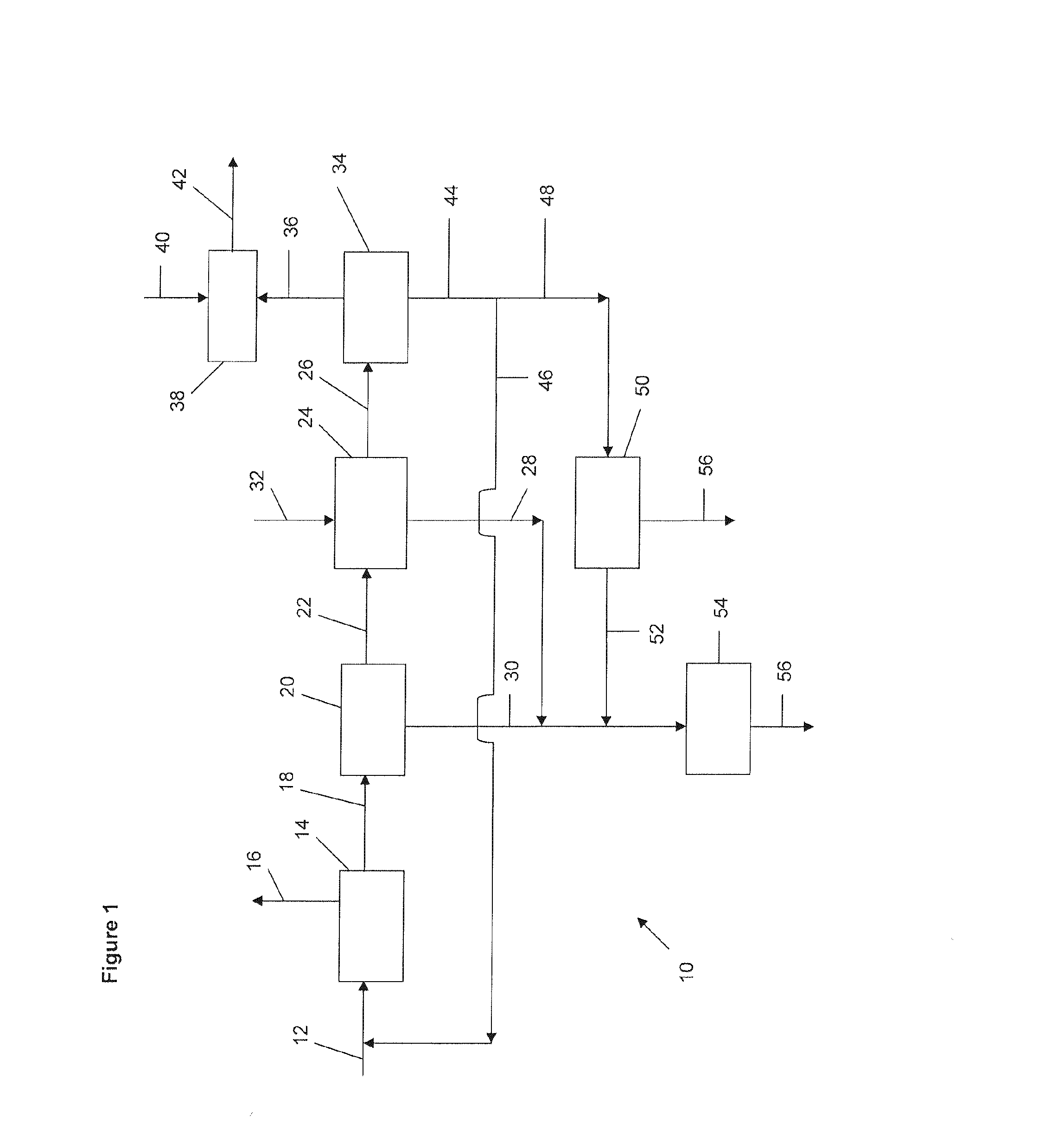
[0021]FIG. 1 shows a system 10 for treating a feedstock 12. The feedstock 12 is typically a waste biomass. The feedstock 12 is treated first in an anaerobic digester 14. The digester 14 converts the feedstock 12 into biogas 16 and digestate 18. Biogas 16 may be used, typically after upgrading, in the system 10 or after being transferred out of the system 10. Examples of suitable feedstock 12 that result in high nutrient content digestate 18 include animal manure, post-consumer food waste, pre consumer food processing waste, biofuels processing by products, agricultural waste, and municipal wastewater sludge, among others. International Publication WO 2012 / 109737 is incorporated by reference.

[0022]The biogas 16 may be flared but it is preferably sent to a biogas processing unit to produce one or more of gas products, heat or power. The biogas processing unit may include one or more treatment units to upgrade the biogas. For example, the biogas may be treated to remove water vapour, p...


PUM

PropertyMeasurementUnit
concentrationsaaaaaaaaaa
concentrationaaaaaaaaaa

Abstract

An apparatus for recovering nutrients or water from digestate comprises one or more solid-liquid separation units, an ammonia stripping device, and a gas scrubbing unit. In a process, digestate is separated into a solids portion and a liquid portion. Ammonia is stripped from the liquid portion and converted into an ammonium salt solution which may be sold or used as, or blended with, a fertilizer product. Optionally, at least part of the remaining liquid portion may be concentrated to produce brine. The brine is mixed with the solids portion. The mixture may be dried and used as, or blended with, a fertilizer product. Optionally, a least part of the remaining liquid portion may be re-used as dilution water in a digester. A solids portion of the digestate, and one or both of an ammonium salt solution and a brine, may be used as fertilizer without thermal drying.

Description

RELATED APPLICATIONS[0001]This application claims priority from U.S. application Ser. No. 13 / 832,737 filed on Mar. 15, 2013; claims priority from, and the benefit of, U.S. provisional application No. 61 / 810,088 filed on Apr. 9, 2013; and, claims priority from International Application Number PCT / CA2012 / 050907 filed on Dec. 18, 2012, all of which are hereby incorporated by reference.FIELD[0002]This specification relates to anaerobic digestion, to the recovery of nutrients from waste biomass, to a fertilizer product, and to removing ammonia from water.BACKGROUND[0003]The following discussion is not an admission that anything discussed below is common general knowledge or citable as prior art.[0004]Various organic waste products contain nutrients that make the waste potentially valuable as fertilizer. For example, some animal manures and organic sludges or slurries could be applied directly to land. However, due for example to the large quantities of material involved relative to the n...

Claims


Application Information

Patent Timeline
Patent Type & Authority Applications(United States)
IPC IPC(8): C02F11/04C01C1/10C01C1/242C02F11/12C05B17/00
CPCC01C1/242C01C1/10C05B17/00C02F11/04C02F11/12C02F2303/02C02F1/20C02F11/121C02F2209/14C02F11/13C05F17/10C05F17/15C05F17/40C05F17/50Y02W10/20Y02W30/40Y02P20/145
Inventor KUMAR, ASHWANIJOSSE, JUAN CARLOSTHEODOULOU, MICHAEL DAVIDROLLINGS-SCATTERGOOD, SASHA MICHAEL
Owner ANAERGIA
Why Eureka
Try Eureka