Packaging laminate, method for producing same, and packaging container produced from the packaging laminate

a packaging laminate and packaging container technology, applied in the direction of lamination, paper/cardboard containers, containers, etc., can solve the problems of increasing the emission of environmentally harmful greenhouse gases, increasing the consumption of energy, and reducing the environmental protection effect of the environment, so as to achieve the effect of not unnecessarily excessive energy consumption

Inactive Publication Date: 2015-12-31
TETRA LAVAL HLDG & FINANCE SA
View PDF4 Cites 8 Cited by
  • Summary
  • Abstract
  • Description
  • Claims
  • Application Information

AI Technical Summary

Benefits of technology

[0014]Another object is to make available a method which is of the type described at the outset but which, in contrast to the known method, can be carried out without unnecessarily excessive consumption of energy, and without the use of substances that are harmful to health and to the environment, in order to achieve and maintain a permanent functional binding between the gas barrier layer and the paper or paperboard layer of the packaging laminate.

Problems solved by technology

A packaging laminate of the known type permits the production of dimensionally stable packaging containers that are product-compatible and consumer-friendly and hold oxygen-sensitive liquid food, for example milk, juice, wine and cooking oil, but are nonetheless associated with disadvantages in terms of both the environment and also processing technology.
An extrusion at elevated temperature (ca 330° C.) entails increased consumption of energy and, consequently, an increased emission of environmentally harmful greenhouse gases (“carbon footprint”).
Once they have actually started, these degradation reactions can proceed to such an extent that the desired ability of the polymer to maintain a permanent binding strength between the aluminium foil and the paper or paperboard layer is lost, and the mechanical strength is thereby also lost.

Method used


Image

  • Packaging laminate, method for producing same, and packaging container produced from the packaging laminate
  • Packaging laminate, method for producing same, and packaging container produced from the packaging laminate
  • Packaging laminate, method for producing same, and packaging container produced from the packaging laminate

Examples


example 1

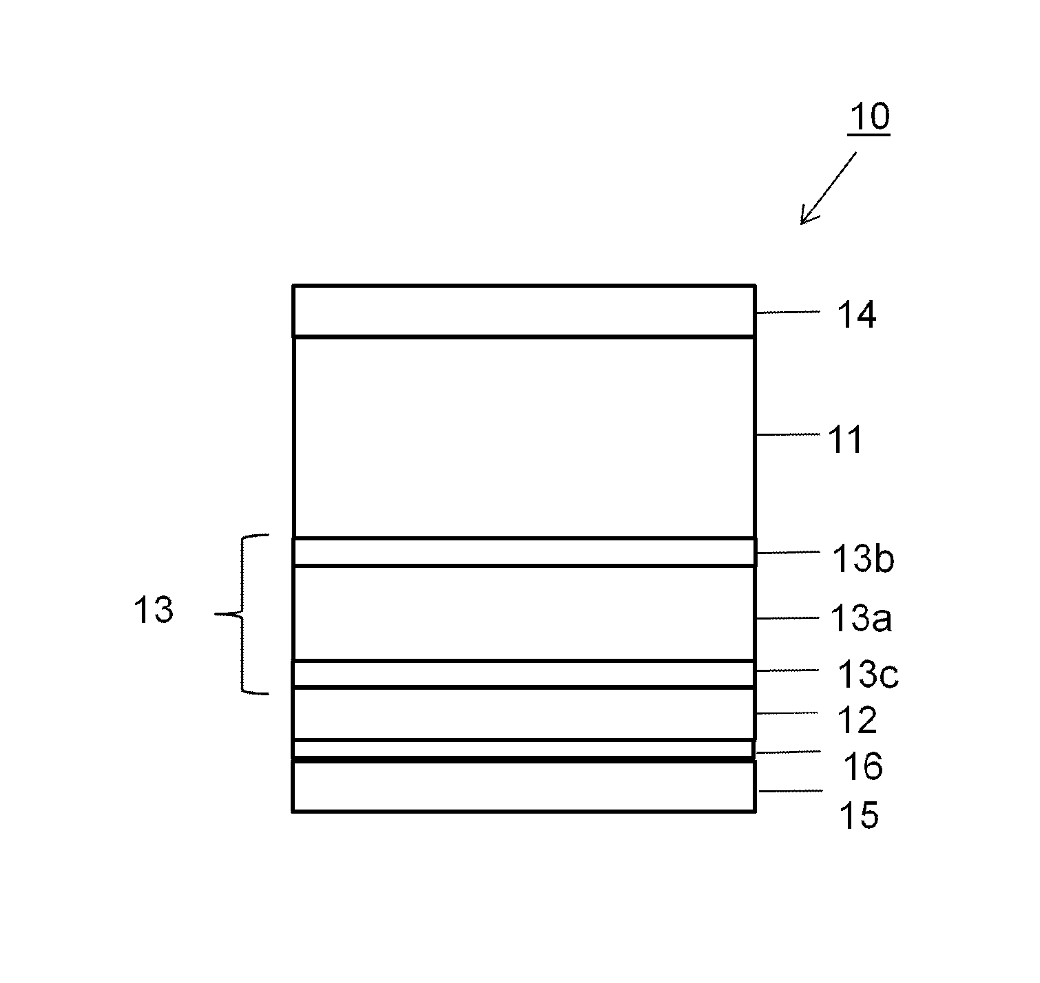
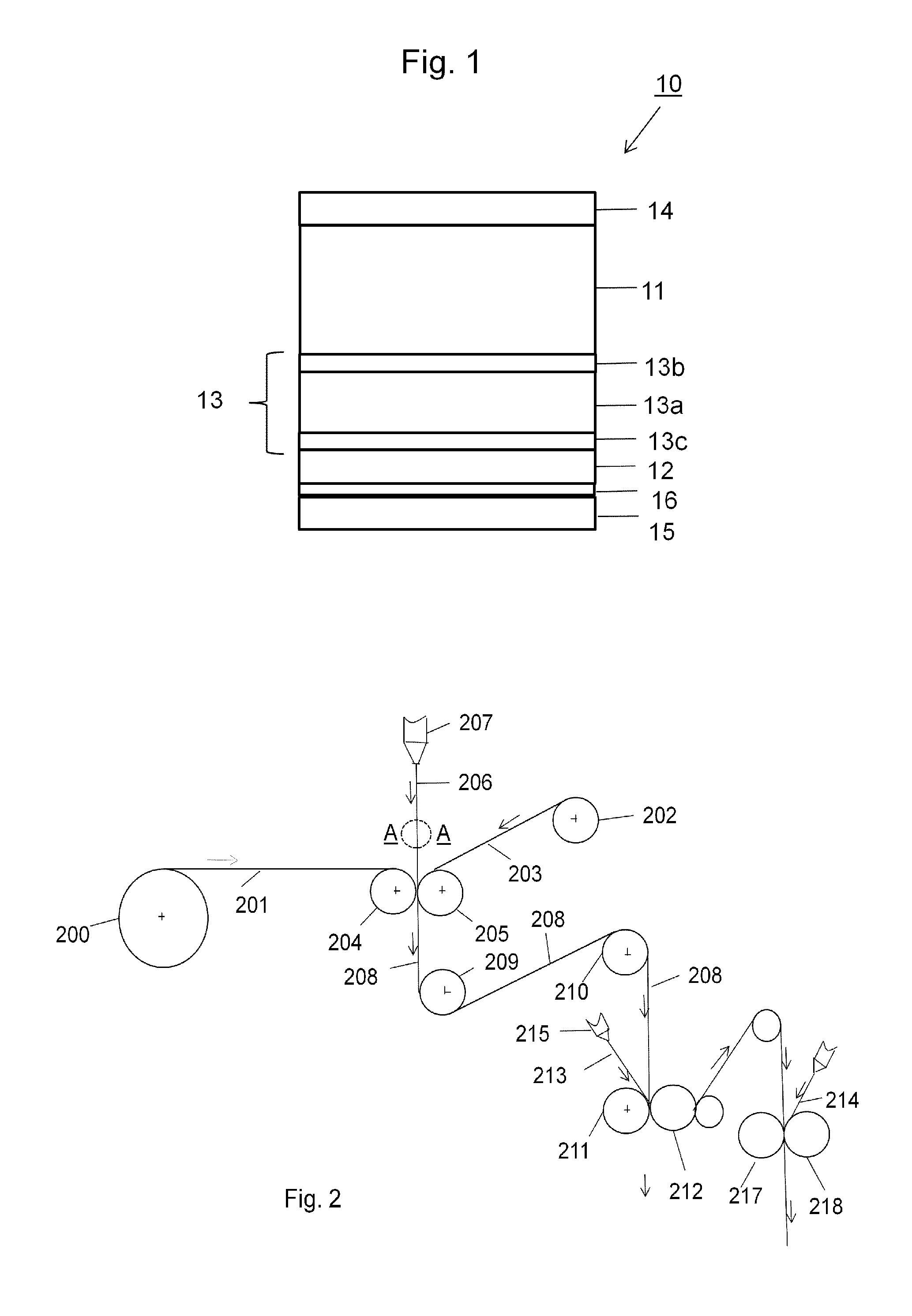
[0092]Packaging laminate 10 was produced with the composition indicated in the following table:

Coating quantity,ReferenceCoating quantity,g / m2 (Example 1sign ing / m2 (referenceaccording toLaminate layerFIGS.example 1)the invention)Low-density141212polyethylene (LDPE)Paperboard11Ethylene-acrylic acid 13b—3copolymer (EAA)(Primacor 3540Dow; with about8 weight-%acrylicacid content)Low-density 13a2010polyethylene (LDPE)(Novex 19N730)(Novex 19N730)(Autoclave-LDPE)Ethylene-acrylic acid 13c3copolymer (EAA)(Primacor 3540Dow)Aluminium foil126.3 μm6.3 μmEthylene-acrylic acid(not 6 6copolymer (EAA)shown)Blend of LDPE and m-151919LLDPE (weight ratio30:70)

[0093]Packaging laminate 10 according to the invention in Example 1 was produced by co-extrusion of the material layers 13a-13c as a three-layer structure, with the material layers included in the sequence 13b / 13a / 13c. This co-extrusion could generally be carried out at an extrusion speed of 200 m / min and at an extrusion temperature of below 310°...

example 2

[0097]Example 1 and reference example 1 were repeated at a web speed of 200 m / min and with two different spacings between the outlet of the extrusion die and the point of contact of the melt curtain with the surface of the web, namely air gaps of 195 mm and 310 mm. Moreover, the examples were repeated with the sole difference that the laminating material in reference example 1 was replaced by a test polymer of LDPE2 produced by polymerization in a tube reactor, which had the expected poor extrusion properties, in the form of a high neck-in, upon extrusion as a single layer of laminating material.

[0098]In Example 2, a laminating material was co-extruded with a central layer of the same LDPE2 and with outer adhesive layers of the same polymer and layer thickness as in Example 1.

[0099]Equivalent packaging properties to those in Example 1 (barrier properties and adhesion) were obtained, and also a considerably improved extrusion process (reduced neck-in) compared to a reference example ...

example 3

[0101]Reference example 2 was repeated with the sole difference that the laminating material was replaced by a polymer LDPE3 (Dow 750 E) which was produced by polymerization in a tube reactor and which, according to all available data and recommendations, is not suitable for extrusion coating and is instead intended for injection moulding and has an MFI of as high as 20 g / 10 min at 2.16 kg, 190° C. As was expected, conventional extrusion lamination could not be carried out with this polymer on account of too much neck-in. In Example 3, a laminating material was instead co-extruded with a central layer of the same LDPE3 and with outer adhesive layers of the same polymer and layer thickness as in Example 2.

[0102]Equivalent adhesion properties were obtained and a considerably improved extrusion process (reduced neck-in), including better than expected and equivalent to reference lamination with a single layer of the autoclave-polymerized LDPE in Example 1. Moreover, in all of Examples ...


PUM

PropertyMeasurementUnit
temperatureaaaaaaaaaa
MFIaaaaaaaaaa

Abstract

Packaging laminate for a packaging container for oxygen-sensitive liquid food, such as milk, juice, wine and cooking oil. The packaging laminate has a layer of paper or paperboard, and a layer serving as gas barrier and composed of a material with barrier properties against gases, in particular oxygen. The layer serving as gas barrier is bonded to the paper or paperboard layer by a lamination layer, which has a central layer of polymer and outer layers of an adhesive on both sides of the polymer layer. The packaging laminate also has outer liquid-tight coatings on both sides of the paper or paperboard layer.

Description

TECHNICAL FIELD[0001]The present invention relates to a method for producing a packaging laminate comprising a paper or paperboard layer and a layer serving as gas barrier, which layers are bonded to each other by a lamination layer, in which method a web of a material with gas barrier properties is brought together with a web of paper or paperboard, and the webs brought together are guided through the nip between two rotatable cylinders, while at the same time a laminating material is applied between the webs in order to permanently bind these to each other.[0002]The invention also relates to a packaging laminate comprising a paper or paperboard layer and a layer serving as gas barrier, which layers are bonded to each other by a lamination layer.[0003]In addition, the invention relates to a packaging container for foods, which packaging container has been produced by folding the packaging laminate.BACKGROUND OF THE INVENTION[0004]A known packaging laminate of the type described abo...

Claims


Application Information

Patent Timeline
Patent Type & Authority Applications(United States)
IPC IPC(8): B32B27/10B32B7/12B32B37/15B32B15/08B32B37/12B32B15/20B32B27/32
CPCB32B37/12B32B2307/7242B32B2317/12B32B2439/70B65D75/26B65D75/48B65D5/064B65D5/067B65D85/80B32B7/12B32B15/08B32B15/20B32B27/10B32B27/32B32B27/327B32B2270/00B32B37/153B32B27/00B32B37/15B29C48/15
Inventor JOHANSSON, HANS
Owner TETRA LAVAL HLDG & FINANCE SA
Why Eureka
Try Eureka