
Best-fit affinity sensorless conversion means or technique for pump differential pressure and flow monitoring

a technology of conversion means and flow monitoring, applied in the direction of positive displacement liquid engine, force/torque/work measurement apparatus, instruments, etc., can solve the problems of not being easy to achieve, time-consuming and laborious, and the conversion error of around 10-20%, and achieve the effect of satisfying accuracy

Active Publication Date: 2016-01-14
FLUID HANDLING
View PDF36 Cites 32 Cited by
  • Summary
  • Abstract
  • Description
  • Claims
  • Application Information

AI Technical Summary

Benefits of technology

The present invention provides a new and unique way to determine pump or system pressure and flow rate based on motor readout values of power and speed. This is done by using a combination of pump and system characteristics equations with an empirical power equation that is based on the pump manufacturer's curve. The sensorless model and technique disclosed herein is much easier to apply for most practical hydronic pumping control and monitoring applications with satisfactory accuracy without the need for instrumentation calibration. The technical effect of this invention is to provide a better and more precise means to measure pump and system pressures and flow rate without the need for expensive and calibration-related instrumentation.

Problems solved by technology

3, on the other hand, yields a conversion error around 10-20% without a need of instrumentation calibration, even though a power distribution data with respect to system coefficient and motor speed is still needed to convert the system coefficient on a varying hydronic system.
Pump sensorless data calibration, including the instrumentation and data acquisition process, is an interesting discussion topic on pump sensorless applications, which may not be easy achievable at all due to the lack of pressure and flow sensors for most pumping applications scenarios.
In fact, it may be quite time consuming and tedious as well to collect the calibration data for a sensorless pump and motor combination product even to do it in manufacturing assembly lines, not to mention using expensive data acquisition instrumentations as well as hydronic pumping testing systems setups.
The pump efficiency under such a varying hydronic system is a changing variable due to motor speed slip under the varying hydronic load as well as some pump mechanical friction induced thermal consumption effects, especially at low speed with system nearly shut off.

Method used


Image

  • Best-fit affinity sensorless conversion means or technique for pump differential pressure and flow monitoring
  • Best-fit affinity sensorless conversion means or technique for pump differential pressure and flow monitoring
  • Best-fit affinity sensorless conversion means or technique for pump differential pressure and flow monitoring

Examples


Embodiment Construction

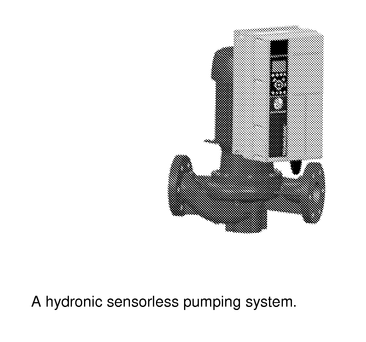
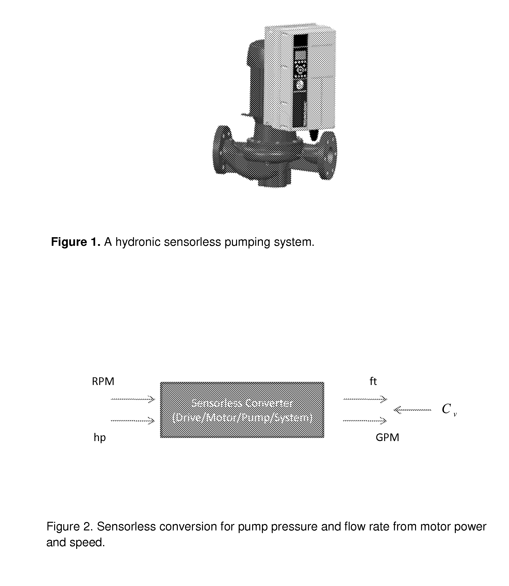
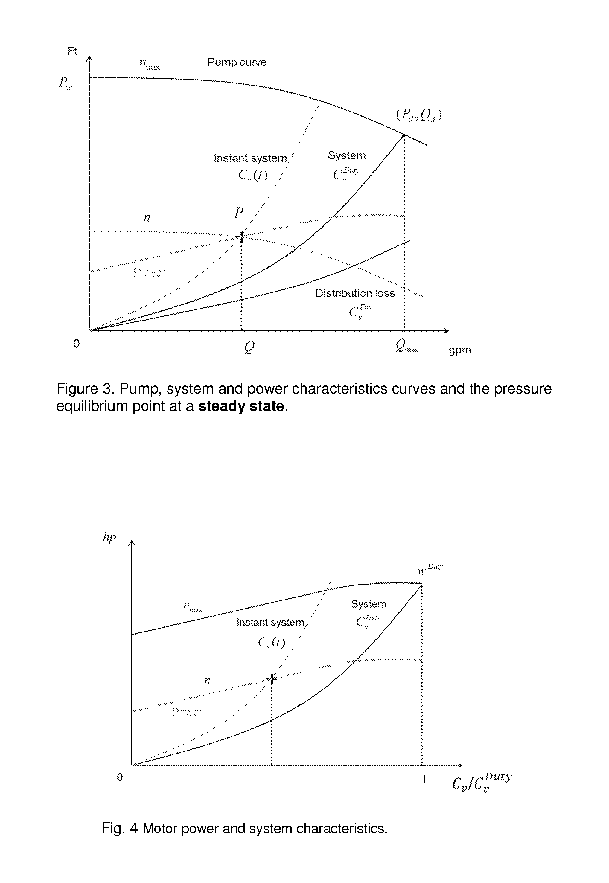
[0040]FIG. 1 shows a hydronic sensorless pumping control system having a combination of a centrifugal pump connected to piping with a flow and a controller, e.g., in which the present invention may be implemented. The sensorless conversion for pump differential pressure and flow rate associated with the equivalent hydronic system characteristics coefficient variable at the discharge of a pump and the motor power and speed at the other end of a motor drive is shown schematically in FIG. 2. Pump, system and power characteristics curves as well as the corresponding pressure equilibrium point of pump and system pressures at a steady state for a close loop system with a static suction pressure are presented schematically in FIG. 3.

[0041]Considering a close loop system with a static suction pressure, the system flow rate and pressure at a motor speed and a system position may be resolved at the steady state equilibrium point of pump and system pressures which is the intersection of the pu...


PUM


Abstract

The present invention provides apparatus, including a hydronic sensorless pumping system, that features a signal processor or processing module configured to receive signaling containing information about motor readout values of power and speed, and also about pump and system characteristics equations together with empirical power equations that are constructed by a polynomial best-fit function together with pump affinity laws based upon a pump curve published by a pump manufacturer; and determine corresponding signaling containing information about a pump or system pressure and a flow rate at the motor readout values of power and speed, based upon the signaling received.

Description

CROSS REFERENCE TO RELATED APPLICATION[0001]This application claims benefit to U.S. provisional application No. 61 / 976,749 (Atty Dckt No. 911-019.014-1 / / F-B&G-X0012US01), filed 8 Apr. 2014, entitled “A Best-fit affinity sensorless conversion means for pump differential pressure and flow monitoring,” which is hereby incorporated by reference in its entirety.[0002]This application is also related to a family of technologies developed by one or more of the inventors and disclosed in the following applications:[0003]1) U.S. application Ser. No. 12 / 982,286 (Atty Dckt No. 911-019.001-1 / / F-B&G-1001), filed 30 Dec. 2010, entitled “Method and apparatus for pump control using varying equivalent system characteristic curve, AKA an adaptive control curve,” which issued as U.S. Pat. No. 8,700,221 on 15 Apr. 2014;[0004]2) U.S. application Ser. No. 13 / 717,086 (Atty Dckt No. 911-019.004-2 / / F-B&G-X0001), filed 17 Dec. 2012, entitled “Dynamic linear control methods and apparatus for variable speed pu...

Claims


Application Information

Patent Timeline
Patent Type & Authority Applications(United States)
IPC IPC(8): F04B51/00G01F1/34
CPCG01F1/34F04B51/00F04B17/03F04B49/065F04B49/103F04B49/106F04D15/0088F15B19/00F16K37/0075G01L5/0061
Inventor CHENG, ANDREW A.GU, JAMES J.SCOTT, GRAHAM A.
Owner FLUID HANDLING
Learn More