Catheter-guided replacement valves apparatus and methods

a replacement valve and catheter-guided technology, applied in the field of catheter-guided replacement valve apparatus and methods, can solve the problems of affecting the normal unidirectional flow of blood in the body, and affecting the normal unidirectional flow of blood in the heart and the rest of the body, so as to reduce the height dimension

Active Publication Date: 2016-02-04
NAVIGATE CARDIAC STRUCTURES
View PDF2 Cites 197 Cited by
  • Summary
  • Abstract
  • Description
  • Claims
  • Application Information

AI Technical Summary

Benefits of technology

[0022]The stent or frame, wherein the valvular mechanism resides or is mounted is also in the same general form. Adopting this cooperating conformation allows the height dimension to be reduced without compromising the flow / pressure properties of the valve while minimizing the intrusion of the device into the left atrium. Given that a diseased mitral annulus could be enlarged 30%-50% above the normal diameter or cross section, causing the valvar leaflets inability to meet and resulting in mitral regurgitation, the “annulus” of the prosthesis should be of similar size to the dilated patient annulus so as to be able to anchor the device fully onto the dilated patient's annulus. However, the conformation does not require a valvular mechanism or a valve that can open and close normally and has the exact same dimensions as the annulus. The device does not need to be cylindrical, but the valve may be located slightly above the annulus not far enough to disrupt the normal function of the left atrium. [TAPE #1]

Problems solved by technology

Such events including infections, structural failures such as tears or disruption of certain components as with the mitral valve chordae, or deformation because of genetic predisposition of valvular material, can disrupt the normal unidirectional flow of blood in the heart and the rest of the body often with fatal consequences.
The invasiveness of open chest and, open heart surgery and post-surgical complications inherent in such surgeries, also places the older population at high risk for mortality.
While the catheter-guided techniques for the aortic and pulmonary valves have been used extensively, now counting over 300,000 patients, these techniques have not yet translated into well-established mitral valve replacement techniques.
The obvious reason for this is the complexity of the mitral valve.
Both of these leaflets and chordal mass are contained within a not-so-continuous structure generally termed the “annulus.” Approach from the atrial side or the ventricular side of the valve to its annular plane poses difficulties of navigation, not only for the approach, but for the accurate deposition of valved stents coaxially (stent lined with the central axis of the mitral valve), and the capture of the necessary leaflet and annular components to remain in place, to seal the periphery between the two chambers, and to provide the necessary function.
Regrettably, a large proportion goes untreated and since the report was written over one million patients have died.
Present day mitral valve repair centers can only handle a few of the afflicted.
This hope was met with many disappointments when assessing the reliability of the safety and more particularly the effectiveness of such procedures.
The results in many cases are only partially satisfactory with a sizable percentage of incomplete repairs of mitral regurgitation.
Others provide reduction of annular dilatation through the introduction of metallic wires through the coronary sinus vein to circumscribe the mitral valve annulus and reduce its size by constriction, but this also met with disappointing results.
A few others purported to correct the condition by repair with minimally invasive procedures but the results are poor at best.
Regurgitation can greatly diminish the efficiency of the heart and is considered a serious, often life-threatening condition.
However, in their final expanded diameter, such stents are still heir to the pressures the tissue may apply and can be deformed inwardly resulting in loss of the function attempted to restore.
In addition, the valved stent must seal the periphery to avoid leakages (some leakages are in effect regurgitation) that can be very damaging to the blood and the health of the patient, and otherwise may require revision or surgery for correction.
These two effects combine to produce mitral regurgitation causing left ventricle overload and that in turn results in left ventricle dilatation and the cycle begins again.
Currently, no prosthetic mitral valve devices have been fully developed and commercialized for placement in a dysfunctional mitral valve or replacement of the native mitral valve function by percutaneous means or catheter-guided means.

Method used


Image

  • Catheter-guided replacement valves apparatus and methods
  • Catheter-guided replacement valves apparatus and methods
  • Catheter-guided replacement valves apparatus and methods

Examples


Embodiment Construction

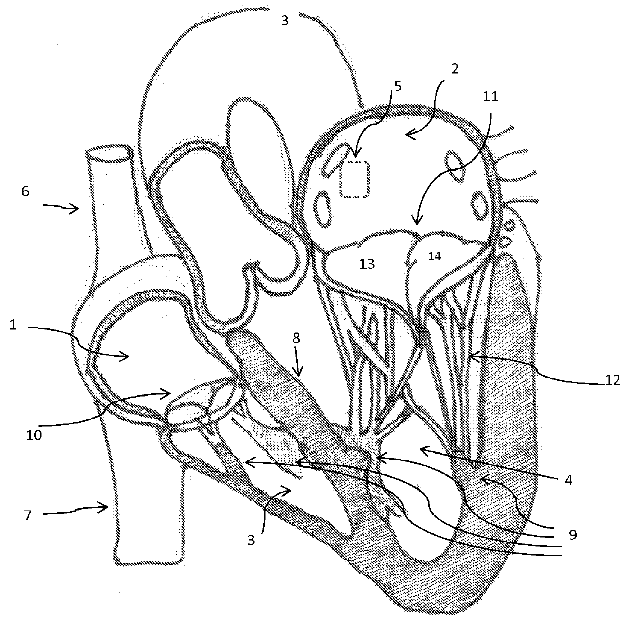
[0046]The invention is a device, several component parts, and a specifically for delivering an artificial heart valve for replacement of a diseased or dysfunctional heart valve. The device including a stent, a stent combined with a valve described herein as a “valved stent” or “valved frame” and the delivery device described below in various designs to facilitate the implantation of a replacement valve assembly that will return function to dysfunctional atrioventricular valves and that heretofore are considered difficult to deliver, deploy and have function with minimal complications. All the inventions described are not limited to atrioventricular valves (mitral and tricuspid valves) but can be applied to replace the function of any of the other cardiac valves.

[0047]One device of the present invention comprises an expandable support member generally called a stent, and a valvar mechanism attached to the main body at the interior of the expandable support member, collectively referr...


PUM


Abstract

The present invention is a replacement mitral valve suitable for catheter-based deployment. The replacement mitral valve has structure and dimensions that are uniquely suited to engage the annulus surrounding the native mitral valve and to restore normal function to a diseased valve. The invention describes the structures and functions of a replacement mitral valve and methods that are adapted for minimally invasive, catheter-based deployment of the valve.

Description

CROSS REFERENCE TO RELATED APPLICATION[0001]This application claims the benefit of U.S. Provisional Application No. 61 / 802,311 filed Mar. 15, 2013, which application is incorporated herein by reference.BACKGROUND[0002]Each of the four heart valves in the human heart, the aortic, and mitral valves on the left side, or the pulmonary and tricuspid valves on the right side can become dysfunctional in many ways at any time. Such events including infections, structural failures such as tears or disruption of certain components as with the mitral valve chordae, or deformation because of genetic predisposition of valvular material, can disrupt the normal unidirectional flow of blood in the heart and the rest of the body often with fatal consequences. Cardiac valves perform a critical function in maintaining every tissue in the body with an adequate supply of nutrients, carried by the blood, as well as maintaining pulsatile flow through the vasculature to perfuse various organs in the body. ...

Claims


Application Information

Patent Timeline
Patent Type & Authority Applications(United States)
IPC IPC(8): A61F2/24
CPCA61F2/2418A61F2/243A61F2/844A61F2230/0067A61F2/86A61F2220/0016A61F2210/0019A61F2002/9665A61F2/2436A61F2/2409A61F2/2412
Inventor QUIJANO, RODOLFO C.CLARK, JASON K.
Owner NAVIGATE CARDIAC STRUCTURES
Why Eureka
Try Eureka