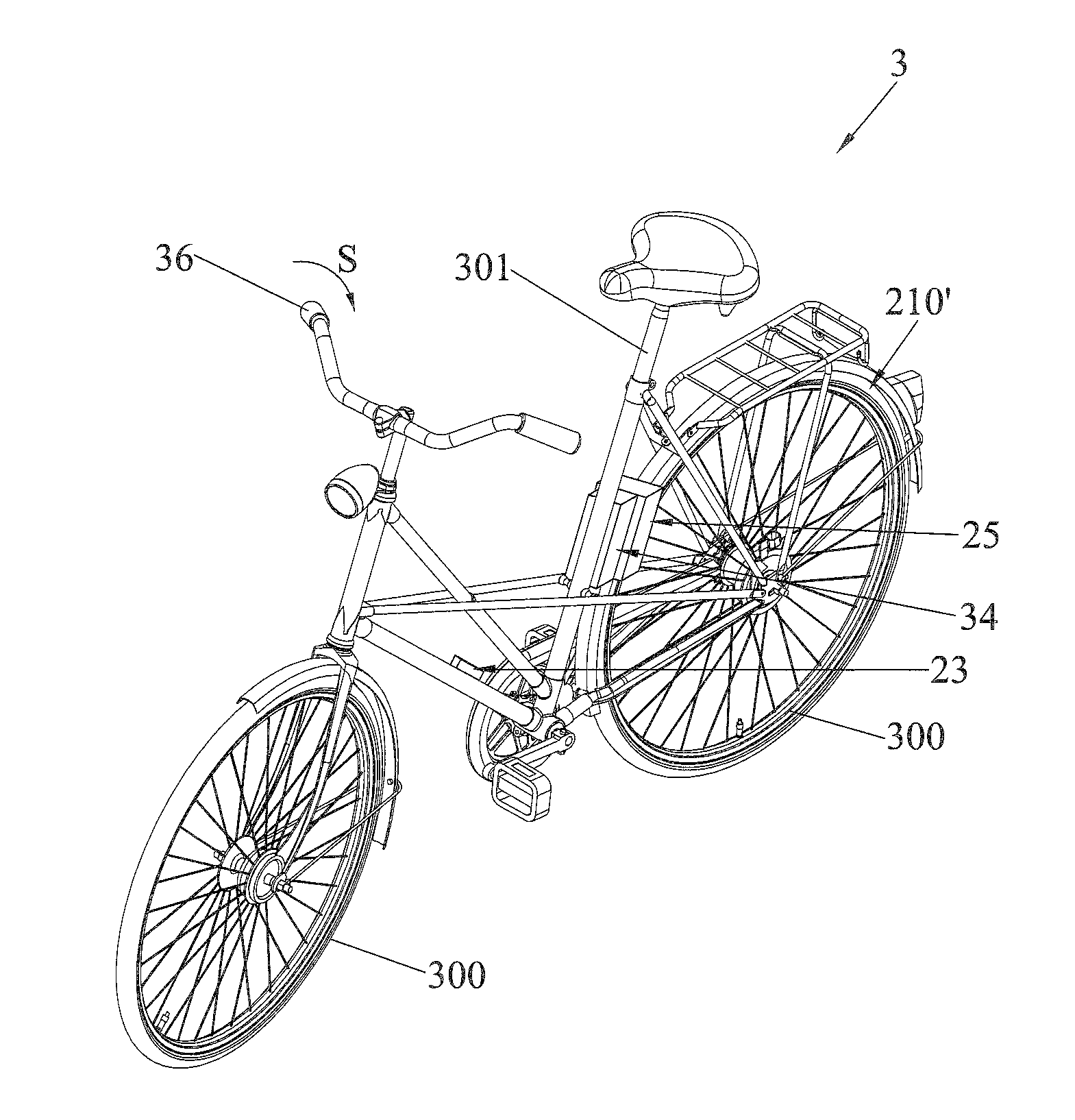
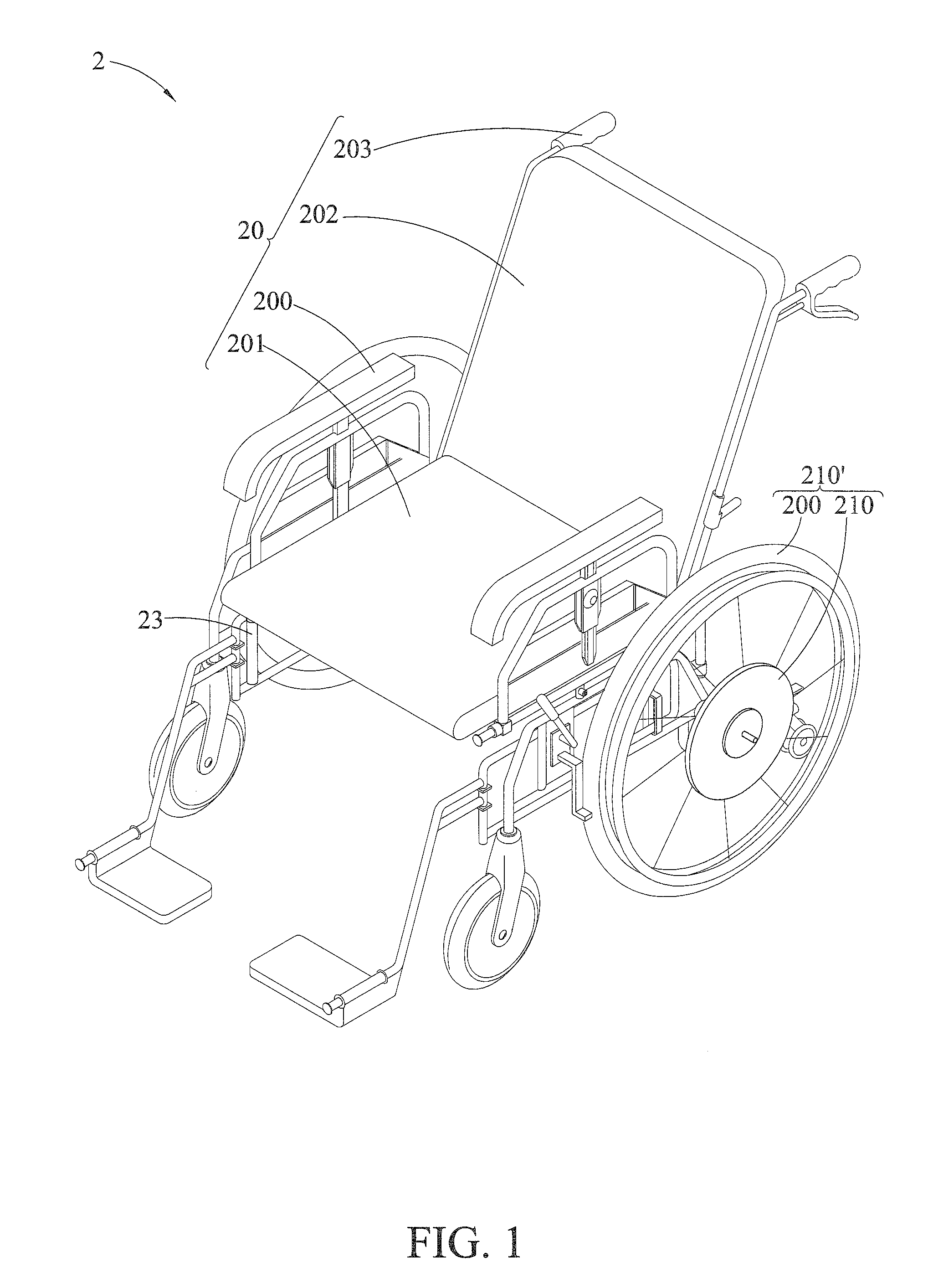
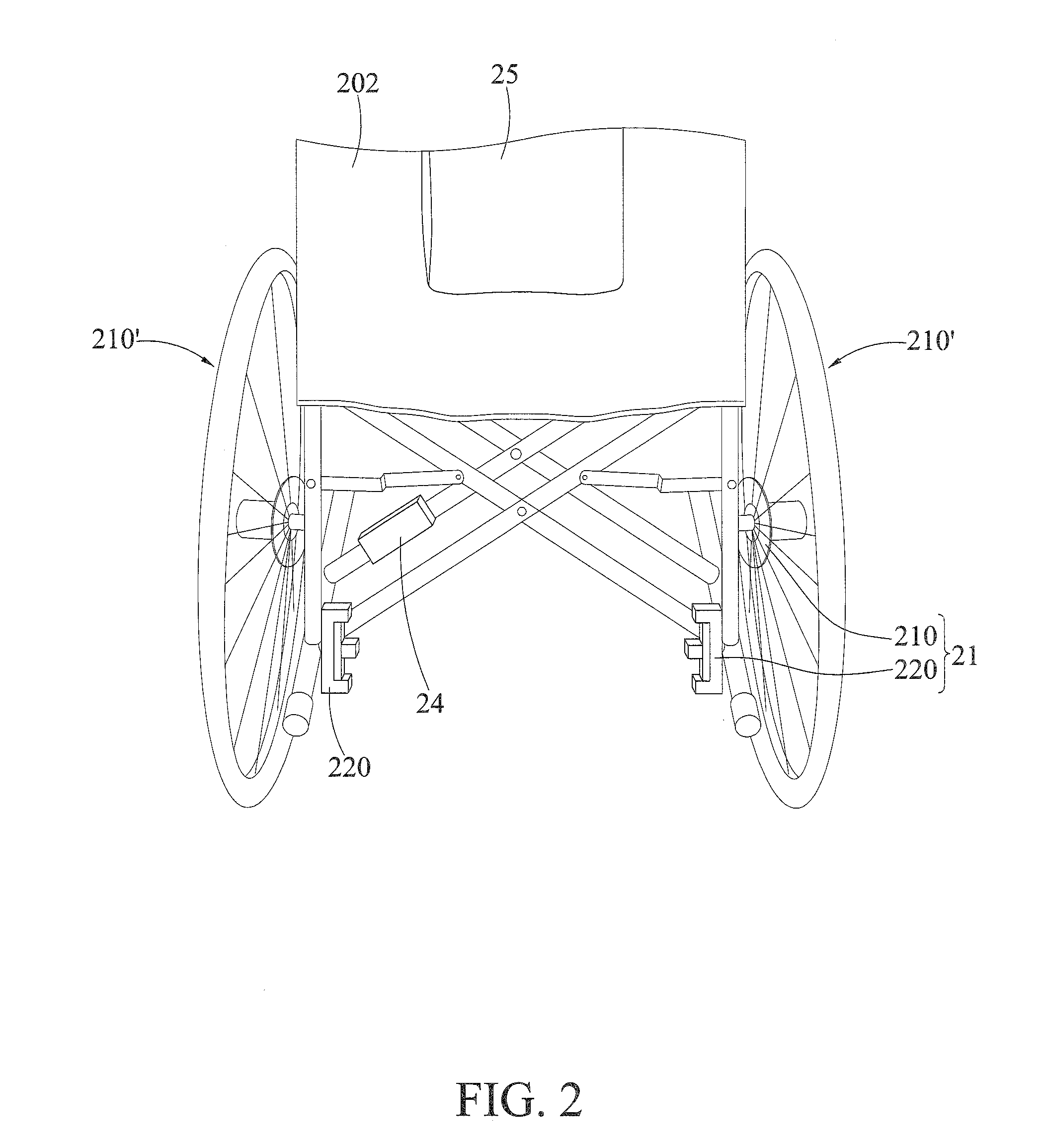
Mobility vehicle and power-assisting system

a technology of mobility vehicle and power assist system, which is applied in the direction of propulsion by batteries/cells, process and machine control, instruments, etc., can solve the problems of wasting energy and physical strength, muscle fatigue, and mechanical kinetic energy being converted into unrecyclable heat energy, etc., to save human labor, easy to be attached and disposed, and widely available and inexpensive

Active Publication Date: 2016-03-03
NATIONAL TSING HUA UNIVERSITY
View PDF16 Cites 23 Cited by
  • Summary
  • Abstract
  • Description
  • Claims
  • Application Information

AI Technical Summary

Benefits of technology

[0011]Given above disadvantages of conventional techniques, the present invention provides a novel power-assisting system, which performs inertia compensation, damping compensation and gravity compensation to save the human labor. In addition, it only requires sensors including a hall-sensing-based encoder which measures the motor speed, a multi-axis accelerometer and a multi-axis gyroscope. Such sensors are extensively used in electronics products, thus are broadl

Problems solved by technology

It takes considerable energy and physical strength when the mobility vehicle is loaded heavily or moves uphill, which causes muscle fatigue.
While, when the mobility vehicle moves downhill, the mechanical kinetic energy is converted to unrecyclable heat energy due to the use of a mechanical brake.
Therefore, the mobility vehicle is often inefficient and energy-wasting in such applications.
However, as far as the conventional power-assisted bicycles and power-assisted wheelchairs are concerned, a force/torque sensor is often required to sense the human power; such sensors are expensive and may not convert the force instantaneously due to the limited bandwidth.
Moreover, the calibration of the sensors is laborious which would cost engineering resources.
However, when the accelerometer detects the inclination angle based on the projection of the gravitational force along the ramp direction, the inclination angle will be inaccurate if the mobility vehicle is operated in an accelerating or decelerating state, or is operated on a bumpy road, because the acce

Method used


Image

  • Mobility vehicle and power-assisting system
  • Mobility vehicle and power-assisting system
  • Mobility vehicle and power-assisting system

Examples


Embodiment Construction

[0033]The following specific embodiments are provided to illustrate the disclosure of the present invention, the advantages and effects can be apparently understood by those skilled in the art after reading the disclosure of this specification.

[0034]It should be understood that, in the specification to the accompanying drawings, the depicted structures, proportions, sizes, etc., are disclosed only to match the content of the specification, and to facilitate the understanding for those skilled in the art, but not to limit the present invention in specific conditions. The depicted structures, proportions, sizes, etc. do not contain specific technical meanings. Any modification of the structure, change of the ratio relation, or adjustment of the size should be involved in the scope of disclosures in this specification without influencing the producible efficacy and the achievable objective of this specification. Also, in this specification, the referred terms such as “upper”, “left”, “...


PUM


Abstract

A mobility vehicle includes a personal mobility vehicle having at least one wheel body and a power-assisting system. The power-assisting system includes an actuation unit, a sensing unit and a signal processing unit. The actuation unit has a motor and a power amplifier geared with the motor. The sensing unit includes a motor rotation speed sensor, a multi-axis accelerometer and a multi-axis gyroscope, so as to sense the velocity, acceleration and the absolute angular velocity of the mobility vehicle in motion in real time. The signal processing unit is connected to the actuation unit and the sensing unit, so as to process the signals of the sensing unit. Then, the actuation unit performs inertia compensation, damping compensation and gravity compensation to the mobility vehicle through a dynamic signal-conditioning algorithm. When the mobility vehicle is actuated by human-power, the power-assisting system assists the power automatically to save human labor.

Description

BACKGROUND OF THE INVENTION[0001]1. Field of the Invention[0002]The present invention relates to power systems, and more specifically, to a power-assisting system of a mobility vehicle.[0003]2. Description of the Related Art[0004]Common personal mobility vehicles, such as bicycles, wheelchairs, baby buggies, trolleys and so on, are moved by human-power with hands or legs. It takes considerable energy and physical strength when the mobility vehicle is loaded heavily or moves uphill, which causes muscle fatigue. While, when the mobility vehicle moves downhill, the mechanical kinetic energy is converted to unrecyclable heat energy due to the use of a mechanical brake. Therefore, the mobility vehicle is often inefficient and energy-wasting in such applications.[0005]Accordingly, power-assisted devices such as power-assisted bicycles or power-assisted wheelchairs are developed. In such devices, the driving wheel is replaced with an electric motor, and the pedaling or hand-propelling is d...

Claims


Application Information

Patent Timeline
IPC IPC(8): B62M6/50A61G5/04B60L11/18B60L50/30
CPCB62M6/50A61G5/041B60L11/1805B62M6/45A61G5/022A61G5/10A61G7/018A61G2203/38B60L50/52Y02T10/70
Inventor YEH, TING-JENHUANG, CHUN-FENGDAI, BANG-HAO
Owner NATIONAL TSING HUA UNIVERSITY
Why Eureka
Try Eureka