Honeycomb structural body and method for manufacturing the same

Active Publication Date: 2016-04-07
NGK INSULATORS LTD
View PDF0 Cites 7 Cited by
  • Summary
  • Abstract
  • Description
  • Claims
  • Application Information

AI Technical Summary

Benefits of technology

[0030]According to the joined body and the method for manufacturing the same of the present invention, the first member and the second member are joined with the oxide ceramic containing a Fe3O4 phase in which a solute component capable of forming a spinel-type oxide with Fe is solid-dissolved. This oxide ceramic is made more thermally stable by the solute component. Therefore, the two members can be more reliably joined. in the method for manufacturing a joined body, a joint layer including a Fe metal powder and a solute component powder which contains a solute component capable of forming a spinel-type oxide with Fe is formed and fired, and thus the two members can be more easily jo

Problems solved by technology

However, since a joining layer of each of the joined bodies disclosed in Patent Literatures 1 to 3 is formed of a metal, there have been problems, such as a low heat resistance, a low oxidation resistance, and a low joining reliability.
In the honeycomb structural bodies disclosed in Patent Literatures 4 to 6, although Cu, Al, Si, and/or the like is used as an electrode material, the heat resi

Method used


Image

  • Honeycomb structural body and method for manufacturing the same
  • Honeycomb structural body and method for manufacturing the same
  • Honeycomb structural body and method for manufacturing the same

Examples


Example

Experimental Examples 1 to 23

[0094]In Experimental Examples 1 to 23, the formation was performed under the conditions shown in Table 1. In Experimental Examples 1 to 10, the composition ratio of Ni, which was the solute component, was changed. In Experimental Examples 11 to 13, a Fe2O3 phase used as the surface layer was not formed. In Experimental Example 14, the pore forming agent was added, and in Experimental Example 15, a Ni metal powder was used as a Ni source. In Experimental Examples 16 to 19, an element other than Ni was uses as the solute component. In Experimental Example 20, a Fe oxide was used as the joining material raw material. In Experimental Examples 21 to 23, the first member was changed.

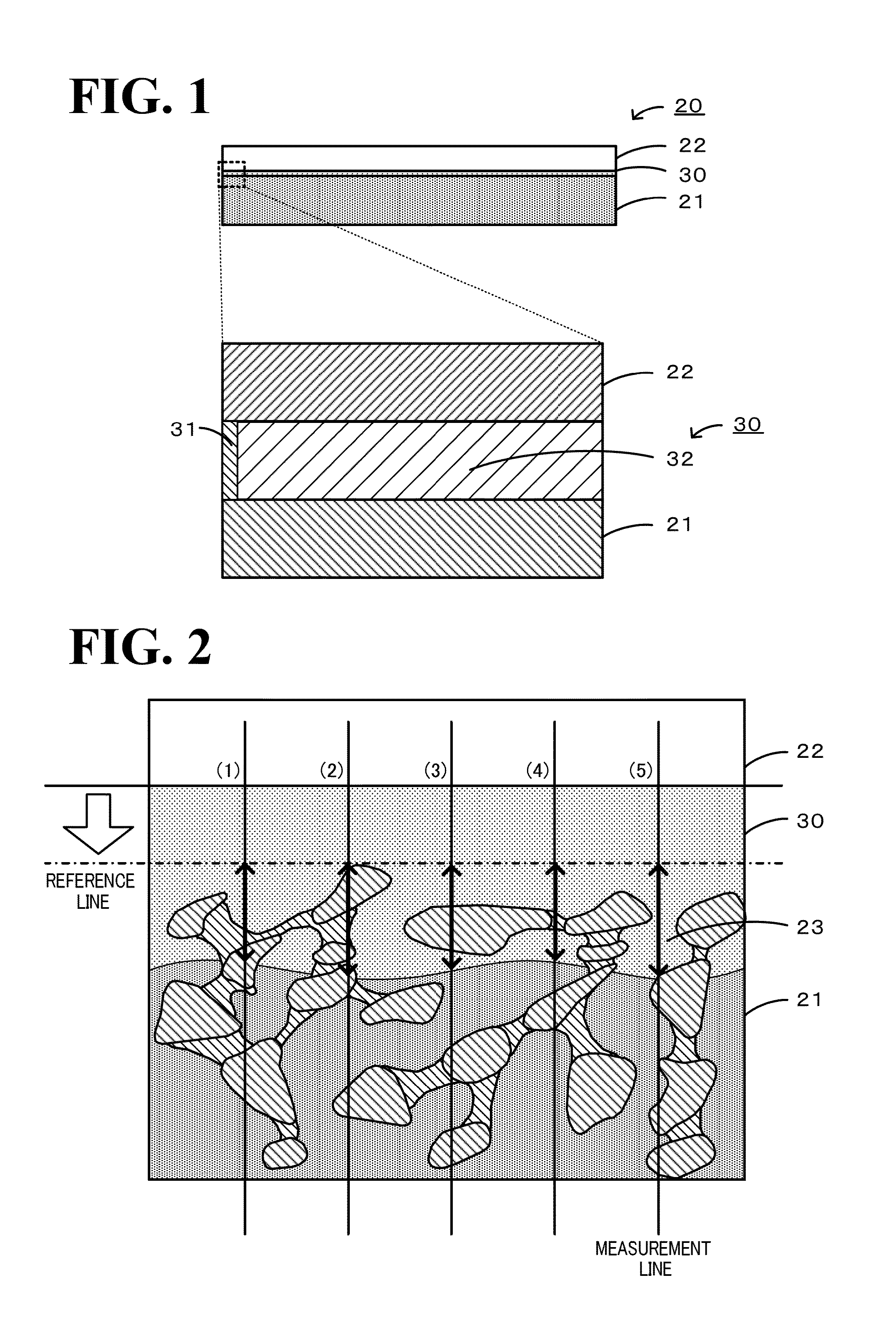
[0095](Identification of Crystal Phase and Calculation of Peak Shift)

[0096]By the use of a rotating anticathode-type x-ray diffraction apparatus (RINT, manufactured by Rigaku Corp.), an x-ray diffraction pattern of the joint portion was obtained. The x-ray diffraction measurement ...

Example

[0101]In Experimental Example 22, after two Al2O3-made porous material bodies each obtained by cutting to have a size of 10×20×40 mm and a SUS430 plate having a thickness of 0.05 mm were joined together using the joining material described above to form the joined body, evaluation was performed by applying a load thereto. In Experimental Example 23, after two LaCrO3-made dense material bodies each obtained by cutting to have a size of 10×20×40 mm and a SUS430 plate having a thickness of 0.05 mm were joined together using the joining material described above to form the joined body, evaluation was performed by applying a load thereto. As for the evaluation of the joining strength, a joining strength of 3.5 MPa or more was ranked as “A”, a joining strength of 2.0 to less than 3.5 MPa was ranked as “B”, and a joining strength of less than 2.0 MPa or a joining strength which could not be measured was ranked as “D”. Incidentally, a joining strength of 3.5 MPa is a mechanical strength of ...

Example

Experimental Examples 24 to 36

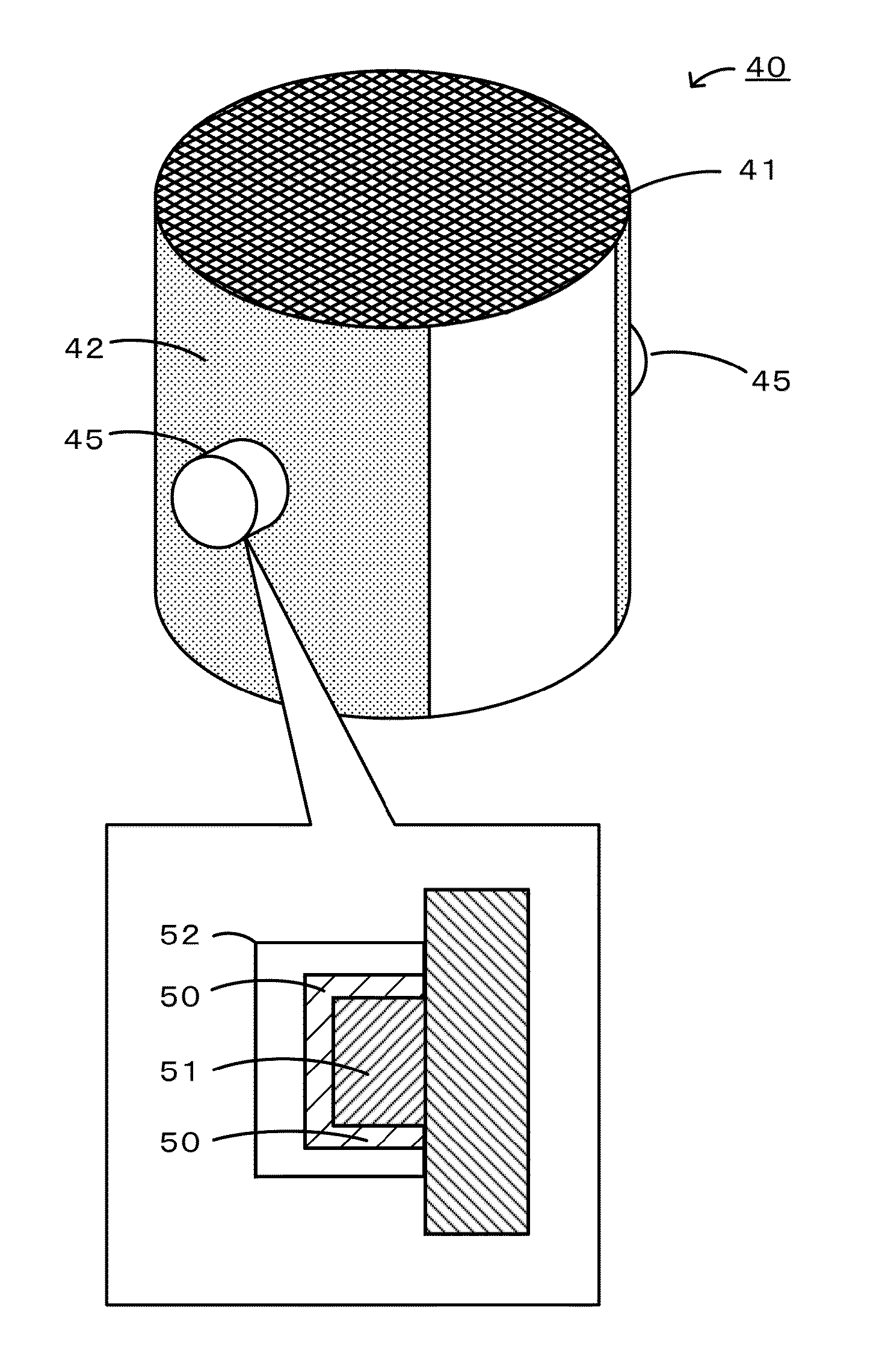
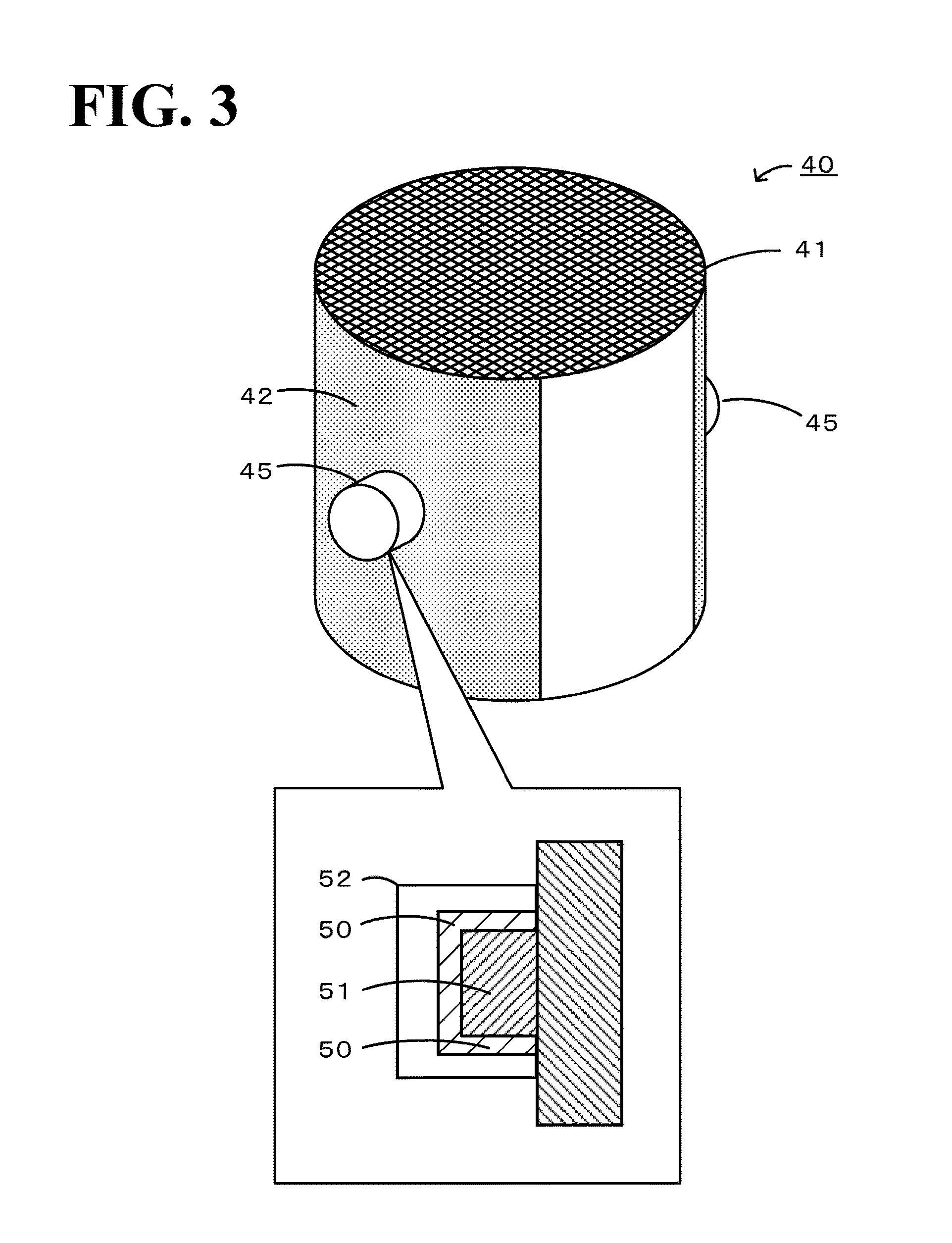
[0109]An electrode containing a Fe3O4 phase was formed on a honeycomb structural body by thermal spraying. As a thermal spraying raw material, Fe2O3 and NiO were fired in the air at 1,200° C. and pulverized into a powder by a ball mill, and the powder thus obtained was granulated to have a D90 of 197.8 μm, a D50 of 83.3 pin, and a D10 of 9.3 μm. As a substrate to be sprayed, a Si-bonded SiC-made honeycomb was used, and on an outer wall thereof, plasma spraying was performed in an air atmosphere under the conditions shown in Table 3. In this case, an electrode having a length of 65 mm, a width of 15 cm, and a thickness t of 12 to 25 μm was formed by thermal spraying on a Si-bonded SiC-made honeycomb having a diameter of 90 mm and a length L of 75 mm. In Experimental Examples 25 to 36, L1 / L was 0.87, and X1 / X was 0.053. In addition, in Experimental Example 24, no electrode was formed without performing thermal spraying, and for example, the electrical res...


PUM

PropertyMeasurementUnit
Percent by massaaaaaaaaaa
Angleaaaaaaaaaa
Electrical conductivityaaaaaaaaaa

Abstract

A honeycomb structural body 40 includes: a partition wall 48 formed of a porous ceramic which forms and defines a plurality of cells 47 each functioning as a flow path of a fluid and extending from one end surface to the other end surface; and an outer circumference wall 49 formed along the outermost circumference, where an oxide ceramic containing a Fe3O4 phase in which a solute component capable of forming a spinel-type oxide with Fe is solid-dissolved is formed.

Description

[0001]The present application claims priority from U.S. provisional application No. 62 / 059,209 filed on Oct. 3, 2014, and U.S. provisional application No. 62 / 075,397 filed on Nov. 5, 2015, the entire contents of both of which are incorporated herein by reference.BACKGROUND OF THE INVENTION[0002]1. Field of the Invention[0003]The present invention relates to a honeycomb structural body and a method for manufacturing the same.[0004]2. Description of the Related Art[0005]Hitherto, as a joined body, a joined body in which a pair of electrodes each formed of a metal layer is provided on a surface of a honeycomb body formed of a porous ceramic has been proposed (for example, see Patent Literature 1). According to this joined body, the metal layer contains Cr and / or Fe, a diffusion layer formed of a metal silicide is present at a boundary portion with the honeycomb body, and the reliability of the electrical connection is ensured in a high-temperature environment. In addition, as the joine...

Claims


Application Information

Patent Timeline
IPC IPC(8): C04B38/00C04B35/26
CPCC04B38/0006C04B35/26C04B37/023C04B2237/068C04B2237/123C04B35/2608C04B2235/3232C04B2235/3275C04B2235/3279C04B2235/3281C04B2235/3284C04B2235/80C04B2235/96C04B2237/406C04B2237/708C04B38/0012B32B3/12B32B7/12B32B9/005B32B9/04B32B15/04B32B15/20B32B2307/202C04B37/005C23C4/12H01R4/58
Inventor IZUMI, YUNIEKOBAYASHI, YOSHIMASA
Owner NGK INSULATORS LTD
Why Eureka
Try Eureka