Hydrogen gas sensor with concentration function and hydrogen gas sensor probe used in same

a technology of hydrogen gas sensor and concentration function, which is applied in the direction of gas analyser construction details, instruments, material heat development, etc., can solve the problems of poor gas selectivity, large explosion risk, and inability to select hydrogen

Inactive Publication Date: 2016-04-14
KIMURA GIKEN KK
View PDF5 Cites 45 Cited by
  • Summary
  • Abstract
  • Description
  • Claims
  • Application Information

AI Technical Summary

Problems solved by technology

However, it has been known that there is a risk of explosion in an extremely broad range when a hydrogen gas exists in the air in an amount of 4.0 to 75.0% (% by volume).
However, since such a sensor reacts to all kinds of reducing gas, it does not have selectivity to hydrogen.
In a hydrogen gas-detection sensor in a catalytic combustion type as shown in Japanese Patent Publication No. 2006-201100, it is so constituted that burning is done at a relatively low temperature using a catalyst in which fine particles such as Pt are carried on an oxide under heating with a heater, and heat of reaction is utilized for detection, but selectivity of the gas is poor since it is reacted with a gas so long as it is a combustible gas.
In particular, a minute amount of a hydrogen gas concentration is to be measured during heating with the heater, it is necessary to control the heating temperature of the heater to be stable, and further a minute temperature rise is to be measured at high temperatures so that problems in the point of precision in the control circuit or the detection circuit are exposed.
Also, it utilizes a catalytic reaction in order to deflagrate at a temperature as low as possible, and the surface state of the catalyst is important in the catalytic reaction but there are problems that the surface state of the catalyst has chang

Method used


Image

  • Hydrogen gas sensor with concentration function and hydrogen gas sensor probe used in same
  • Hydrogen gas sensor with concentration function and hydrogen gas sensor probe used in same
  • Hydrogen gas sensor with concentration function and hydrogen gas sensor probe used in same

Examples


embodiment 1

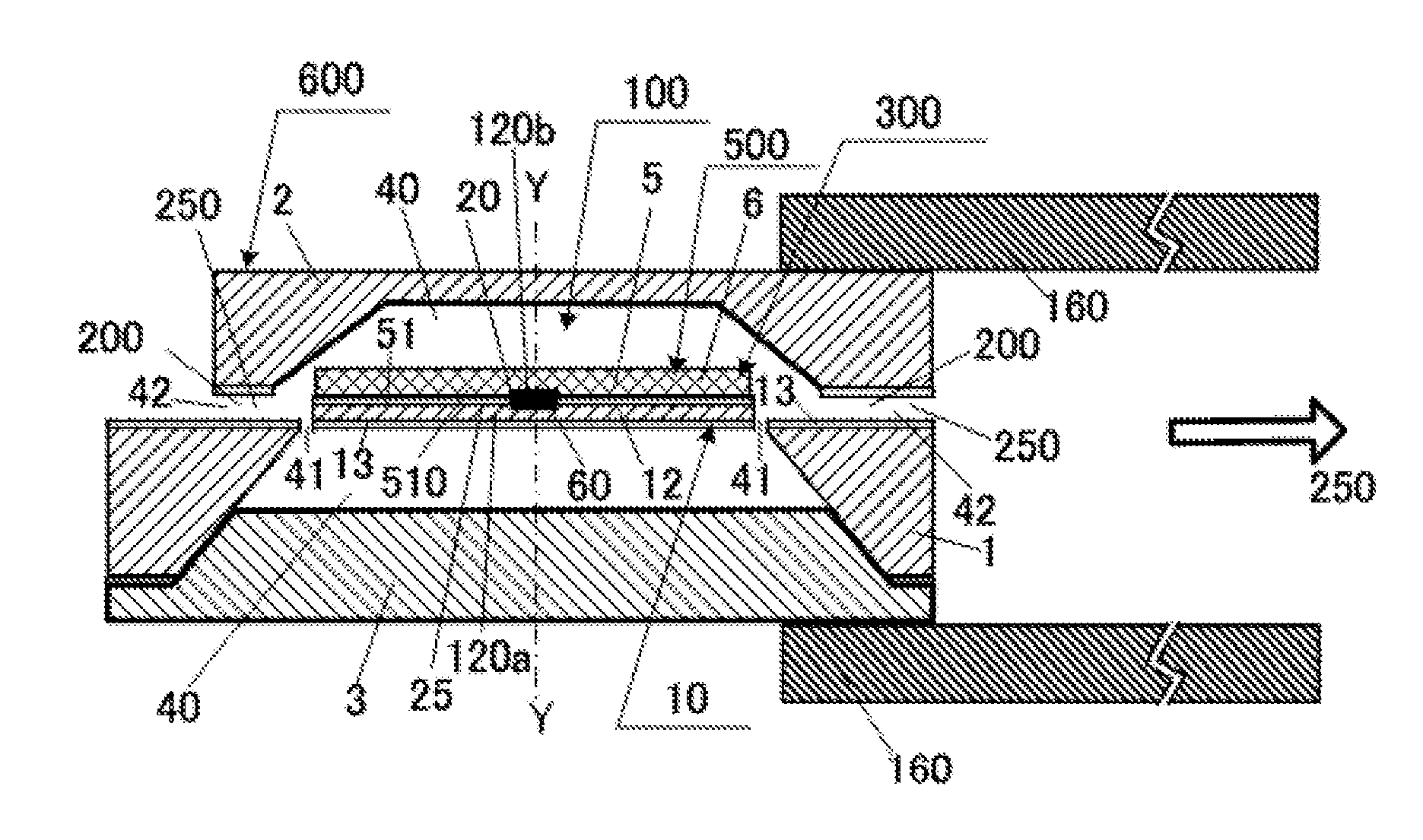
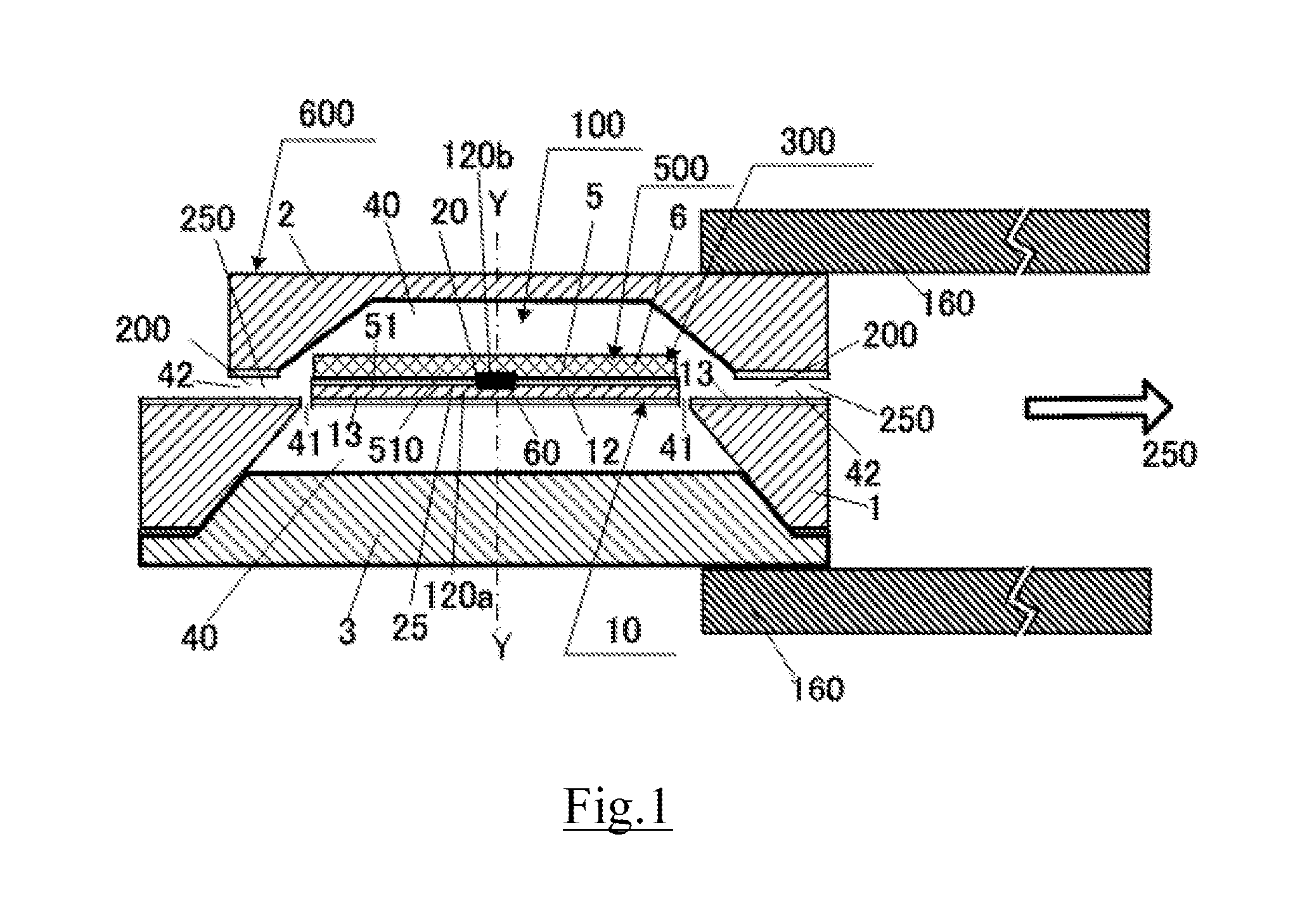
[0056]FIG. 1 is a cross-sectional schematic view illustrating an embodiment of the hydrogen gas sensor probe 600 equipped with the tube 160 characterizing the hydrogen gas sensor in the present invention. FIG. 2 is a cross-sectional schematic view along Y-Y line in FIG. 1. FIG. 3 is a plane schematic view illustrating an embodiment of the substrate 1 in the hydrogen gas sensor probe 600 illustrated in FIG. 1 and FIG. 2. Here, an SOI substrate is used as the substrate 1 and the thin film 10 is crosslinking the cavity 40, being thermally separated from the substrate 1 and floating in the air. The thin film 10 is equipped with the heater 25 and the concentration part 300 having the temperature sensor 20 and the hydrogen absorber 5.

[0057]Here, a thermocouple in which the heater 25 and the temperature sensor 20 are partially shared as the temperature differential sensor 20 is formed and Joule heating is performed by feeding a current to the heater 25. Moreover, the concentration part 300...

embodiment 2

[0065]FIG. 4 is a cross-sectional schematic view illustrating another embodiment of the hydrogen gas sensor probe 600 equipped with the tube 160 characterizing the hydrogen gas sensor in the present invention. FIG. 5 is a plane schematic view illustrating an embodiment of the cover 2 equipped with the hydrogen gas sensor element 500 in the hydrogen gas sensor probe 600 illustrated in FIG. 4. In the cover 2, the SOI layer 12 is made of silicon single crystal substrates. The major difference from the hydrogen gas sensor probe 600 in embodiment 1 illustrated in FIG. 1 to FIG. 3 is as follows. In embodiment 1, the heater 25 and the concentration part 300 having the temperature sensor 20 and the hydrogen absorber 5 formed in the crosslinking thin film 10 are used also as the hydrogen gas sensor element 500. Here, the hydrogen gas sensor element 500 is configured by forming the heater 26 and the hydrogen gas detection part 510 having the temperature sensor 21 and the hydrogen sensitive la...

embodiment 3

[0069]FIG. 6 is a cross-sectional schematic view illustrating another embodiment of the hydrogen gas sensor probe 600 equipped with the tube 160 characterizing the hydrogen gas sensor in the present invention. In the present embodiment, a hydrogen gas sensor of a FET type is used as the hydrogen gas sensor element 500 in embodiment 2, an SOI substrate is used for the cover 2 as in embodiment 2, and MOSFET is formed as the hydrogen detection part 510 by using the SOI layer 12. Moreover, a platinum film a work function of which changes when absorbing hydrogen is used as the hydrogen sensitive layer 6. The other structures are completely the same as in embodiment 2. The operation principle of a hydrogen gas sensor of a FET type is as follows. The platinum film a work function of which mainly changes equivalently when absorbing hydrogen on the gate oxide film of MOSFET is formed as the hydrogen sensitive layer 6. The change in a work function caused by surface adsorption of hydrogen gas...


PUM


Abstract

A hydrogen gas sensor element and a hydrogen gas concentration part which has, on a membrane thermally isolated from a substrate, a heater, a temperature sensor and a hydrogen gas absorbing substance are provided in the same microchamber. Hydrogen gas is released from the concentration part and highly concentrated due to heat applied by the heater, and the highly concentrated hydrogen gas is measured by the hydrogen gas sensor element. Because the hydrogen gas absorbing substance exhibits selectivity for hydrogen gas, there is no need for the hydrogen gas sensor element to exhibit selectivity for hydrogen gas. An airflow limiting part is provided in the exit/entrance opening of the microchamber, whereby dilution of hydrogen gas by the entrance of external airflow is prevented. Introduction of the gas to be investigated into the microchamber is performed at predetermined intervals using an introduction means such as a pump.

Description

CROSS-REFERENCE TO RELATED APPLICATIONS[0001]This application is a U.S. National Stage Application of International Application No. PCT / JP2014 / 063617, filed on May 22, 2014, which claims priority to Japanese Patent Application No. 2013-109375, filed on May 23, 2013. The entire disclosures of the above applications are incorporated herein by reference.BACKGROUND[0002]1. Technical Field[0003]The present invention relates to a hydrogen gas sensor and a hydrogen gas sensor probe used in the same. More specifically, the present invention relates to a hydrogen gas sensor and its sensor probe used for a hydrogen gas leak detector and the like which has high selectivity to hydrogen gas and which also has high sensitivity obtained by concentrating hydrogen gas in external gas.[0004]2. Background Art[0005]The concentration of hydrogen gas, also called H2, is about 0.5 ppm in natural air. This value is smaller than that of helium, which is about 5 ppm. Therefore, hydrogen gas is suitable for a...

Claims


Application Information

Patent Timeline
IPC IPC(8): G01N25/20
CPCG01N25/20G01N33/005G01N2033/0019G01N27/16G01N27/4141G01N25/4893
Inventor KIMURA, MITSUTERU
Owner KIMURA GIKEN KK
Why Eureka
Try Eureka