Implantable nasal stimulator systems and methods

a technology of stimulator and nasal cavity, applied in the field of implantable nasal stimulator system and method, can solve the problems of ocular discomfort, visual disturbance, reduction of vision-related quality of life, etc., and achieve the effect of reducing the diameter of the lumen and preventing the obstruction of the view

Active Publication Date: 2016-04-28
OCULEVE
View PDF11 Cites 47 Cited by
  • Summary
  • Abstract
  • Description
  • Claims
  • Application Information

AI Technical Summary

Benefits of technology

[0013]In some variations, the devices described here comprise devices for dissecting tissue. Some of these devices comprise a shaft comprising a distal end and a proximal end, a blade positioned at the distal end of the shaft, and a lumen, where the lumen extends distally from an opening at the proximal end of the shaft, and the lumen is configured to receive an endoscope shaft therewithin. In some variations, at least a portion of the blade is transparent. In some variations, the blade comprises an edge and a face, and the face is an area at least partially enclosed by the edge. In some variations, the face of the blade is an opening, and in some of these variations, the blade further comprises a window that at least partially covers the face. In some variations where the face is an opening, the device further comprises a barrier positioned at least partially within a distal portion of the lumen, and the barrier is configured to prevent obstruction of a view from the endoscope shaft. In some of these variations, the barrier comprises a liquid polymer configured to solidify after delivery into the device. In some variations, the face is a solid surface that is integral with the edge, and the blade does not comprise any external openings. In some variations, the device comprises a sleeve configured to cover at least a portion of the blade. In some variations, the device comprises a least one tube configured to provide irrigation or suction. In some variations, the device comprises an attachment mechanism configured to releasably attach the device to the endoscope shaft. In some of these variations, the attachment mechanism comprises a compressible section configured to change a diameter of the lumen. In some of these variations, the attachment mechanism comprises a screw portion and a nut portion, and the screw portion and the nut portion comprise mating threads. In some of these variations, the attachment mechanism is configured to compress the compressible section and decrease the diameter of the lumen when the screw portion and the nut portion are screwed together. In some variations, the compressible section comprises deflectable wings. In some variations, the screw portion comprises the compressible section. In some of these variations, a proximal section of the shaft comprises the screw portion and the nut portion.

Problems solved by technology

DED results from the disruption of the natural tear film on the surface of the eye, and can result in ocular discomfort, visual disturbance and a reduction in vision-related quality of life.
Activities of daily living such as driving, computer use, housework and reading have also been shown to be negatively impacted by DED.
Patients with severe cases of DED are at risk for serious ocular health deficiencies such as corneal ulceration, and can experience a quality of life deficiency comparable to that of moderate-severe angina.
DED is progressive in nature, and fundamentally results from insufficient tear coverage on the surface of the eye.
This poor tear coverage prevents healthy gas exchange and nutrient transport for the ocular surface, promotes cellular desiccation and creates a poor refractive surface for vision.
Poor tear coverage typically results from: 1) insufficient aqueous tear production from the lacrimal glands (e.g. secondary to post-menopausal hormonal deficiency, auto-immune disease, LASIK surgery, etc.), and / or 2) excessive evaporation of aqueous tear resulting from dysfunction of the meibomian glands.
This inflammatory response induces apoptosis of the surface cells which in turn prevents proper distribution of the tear film on the ocular surface so that any given tear volume is rendered less effective.
This initiates a vicious cycle where more inflammation can ensue causing more surface cell damage, etc.
Additionally, the neural control loop, which controls reflex tear activation, is disrupted because the sensory neurons in the surface of the eye are damaged.
There is a wide spectrum of treatments for DED, although without substantial efficacy for treatment of the condition.
Despite these treatment options, DED continues to be considered one of the most poorly treated diseases in ophthalmology.

Method used


Image

  • Implantable nasal stimulator systems and methods
  • Implantable nasal stimulator systems and methods
  • Implantable nasal stimulator systems and methods

Examples


example # 1

Example #1

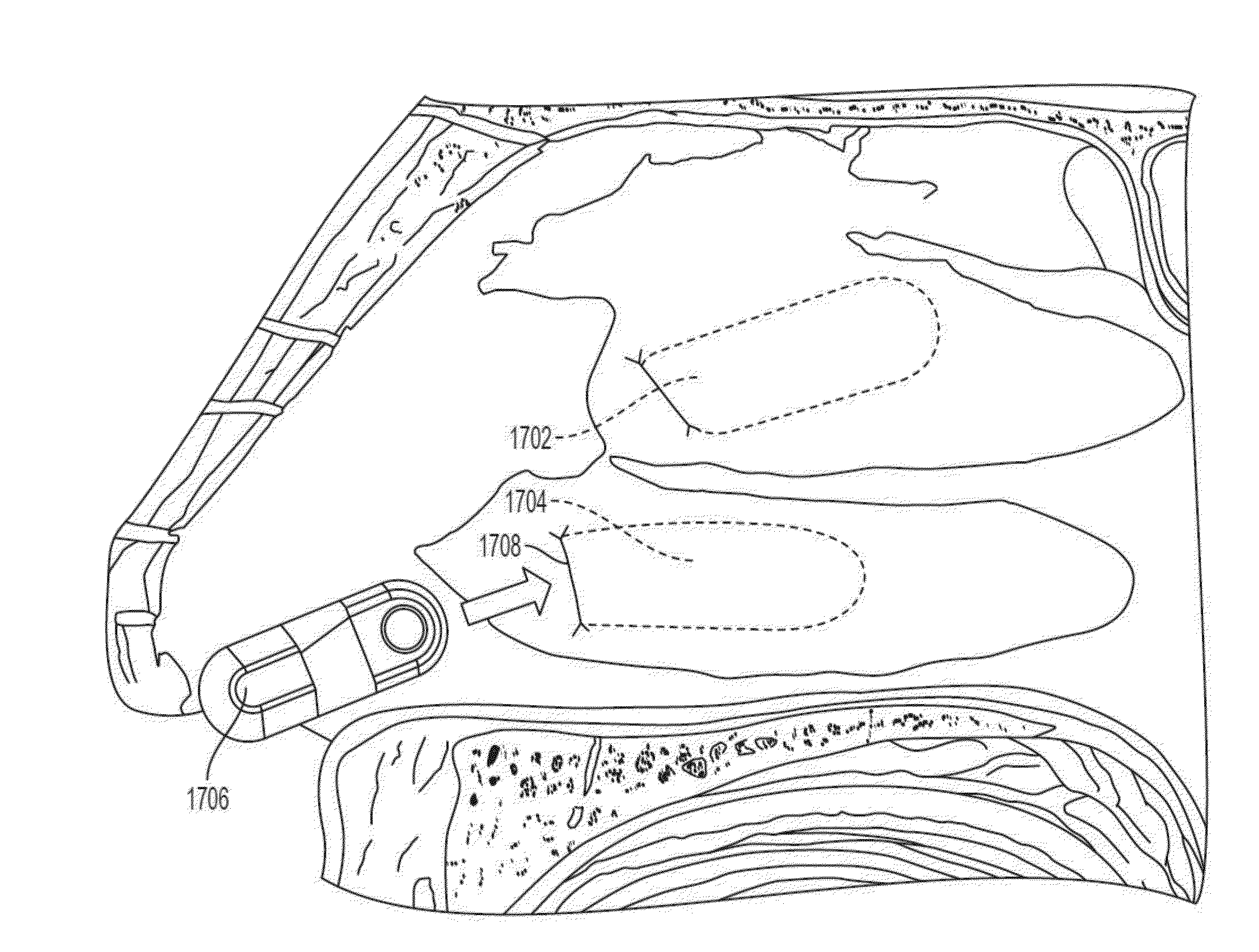
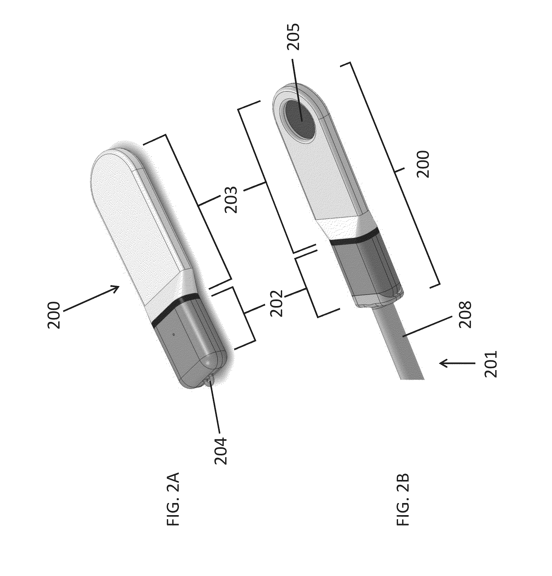
[0211]Two goats were implanted under sterile conditions with a microstimulator and stimulated at least once weekly for 33 days while collecting Schirmer score data to quantify tear production. A Schirmer score recorded in millimeters was determined by using Schirmer test strips, with a greater distance corresponding to greater tear production. The microstimulator implanted was similar to the microstimulator (200) of FIGS. 2A and 2B. The microstimulator was composed primarily of medical grade silicone, titanium (CP Grade 2), and titanium nitride-coated titanium. The microstimulator dimensions were approximately 17 mm×5 mm×2 mm (L×W×H) and the approximate total surface area was 190 mm2. The microstimulator was placed into the left nasal cavity in both animals, below the submucosa of the nasal septum, in one animal on the cartilage and in the other animal on the bony part of the septum.

[0212]Using an electrical probe similar to the electrical probe (1100) of FIG. 11, the desi...

example # 2

Example #2

[0220]Four goats were each implanted with one functional microstimulator and four non-functional replica implants, all of which remained in place for a 49-day study period. An objective of the study was to determine the efficacy of electrical stimulation using a microstimulator operating at 1.2 mA. In addition, surgical tools and techniques for implantation and explantation were evaluated. The microstimulator implanted was similar to the microstimulator (200) of FIGS. 2A and 2B. The microstimulator was composed primarily of medical grade silicone, titanium (CP Grade 2), and titanium nitride-coated titanium. The microstimulator dimensions were approximately 17 mm×5 mm×2 mm (L×W×H) and the approximate total surface area was 190 mm2. The replica implants had approximately the same dimensions and surface area as the microstimulator, but they were composed entirely of silicone.

[0221]For each goat, the implantation site for the microstimulator was determined using an electrical ...

example # 3

Example #3

[0224]A human cadaver study was performed to evaluate surgical tools and techniques for implanting a microstimulator similar to the microstimulator (200) of FIGS. 2A and 2B. This study indicated that an implantation procedure similar to those described with respect to Examples #1 and #2 could be successfully performed on human anatomy. For example, a tissue pocket was formed adjacent to the nasal septum and the microstimulator was implanted using an implantation tool similar to the implantation tool (3000) of FIGS. 27A-27E. FIGS. 29A-29C are fluoroscopic images obtained during this procedure. FIG. 29A depicts the formation of a tissue pocket in the nasal cavity using a dissection tool with a blunt blade (3400). FIG. 29B shows a microstimulator (3402) attached to the distal end of an implantation tool (3404) as the microstimulator (3402) is inserted into the tissue pocket. FIG. 29C depicts the microstimulator (3402) implanted in the nasal tissue pocket after the implantatio...


PUM


Abstract

Described here are systems, devices, and methods for implanting a nasal stimulator into nasal tissue and electrically stimulating nasal tissue. In some variations, a nasal microstimulator implantation system may comprise an implantation tool and an implantable microstimulator. An implantation tool may comprise a shaft and features to releasably attach a microstimulator. A microstimulator may comprise a passive stimulation circuit and one or more electrodes. In other variations, a nasal implantation system may additionally comprise one or more additional devices, such as a controller, an electrical probe, and/or a dissection tool.

Description

CROSS-REFERENCE TO RELATED APPLICATIONS[0001]This application claims priority to U.S. Provisional Application No. 62 / 067,391, filed on Oct. 22, 2014, and titled “IMPLANTABLE NASAL STIMULATOR SYSTEMS AND METHODS,” which is hereby incorporated by reference in its entirety.FIELD[0002]The present invention relates generally to systems, devices, and methods for implanting a nasal stimulator into nasal tissue and electrically stimulating nasal tissue for the treatment of indications such as dry eye.BACKGROUND[0003]Dry Eye Disease (“DED”) is a condition that affects millions of people worldwide. More than 40 million people in North America have some form of dry eye, and many millions more suffer worldwide. DED results from the disruption of the natural tear film on the surface of the eye, and can result in ocular discomfort, visual disturbance and a reduction in vision-related quality of life. Activities of daily living such as driving, computer use, housework and reading have also been sh...

Claims


Application Information

Patent Timeline
Patent Type & Authority Applications(United States)
IPC IPC(8): A61N1/36A61N1/375A61N1/372
CPCA61N1/36046A61N1/3606A61N1/37205A61N1/3756A61N2001/37294
Inventor FRANKE, MANFREDLOUDIN, JAMES DONALDKUZMA, JANUSZYUN, PAUL TAEHYUNACKERMANN, DOUGLAS MICHAEL
Owner OCULEVE
Why Eureka
Try Eureka