Automated tem sample preparation

a sample preparation and automatic technology, applied in the field of automatic preparation of samples, can solve the problems of destroying much of the original sample, bending the sample, over-milling, etc., and achieve the effect of improving the automated performan

Active Publication Date: 2016-05-19
FEI CO
View PDF4 Cites 15 Cited by
  • Summary
  • Abstract
  • Description
  • Claims
  • Application Information

AI Technical Summary

Benefits of technology

[0016]An object of the invention is the automation of part or all of the sample preparation procedure. Because existing manual work flows are difficult to automate, the invention includes new methodologies specifically designed to make automation possible. Sample preparation includes several steps, and this specification describes improvements in several steps. Some embodiments of the invention involve the use of machine vision to determine the positions of the lamella, the probe, and/or the TEM grid to guide the attachment of the probe to the lamella and the attachment of the lamella to the TEM grid. In some embodiments, reference structures known as “fiducials,” formed by a charged particle beam on the lamella and/or the probe, can be used t

Problems solved by technology

Because TEM samples are very thin, preparation of the samples can be delicate, time consuming work.
Thickness variations in thin samples, particularly samples less than 100 nm thick, can result in sample bending, over-milling, or other catastrophic defects.
These methods are disadvantageous because they often require that the starting material be sectioned into smaller and smaller pieces, thereby destroying much of the original sample.
The process of creating and extracting a lamella and transferring it to the sample grid is a delicate and time-consuming procedure, often requiring about 45 to 90 minutes per sample, and requiring the constant operator attention of a skilled operator.
Thus, even though the information that can be gained through TEM analysis can be very valuable, the process has been prohibitively

Method used


Image

  • Automated tem sample preparation
  • Automated tem sample preparation
  • Automated tem sample preparation

Examples


Embodiment Construction

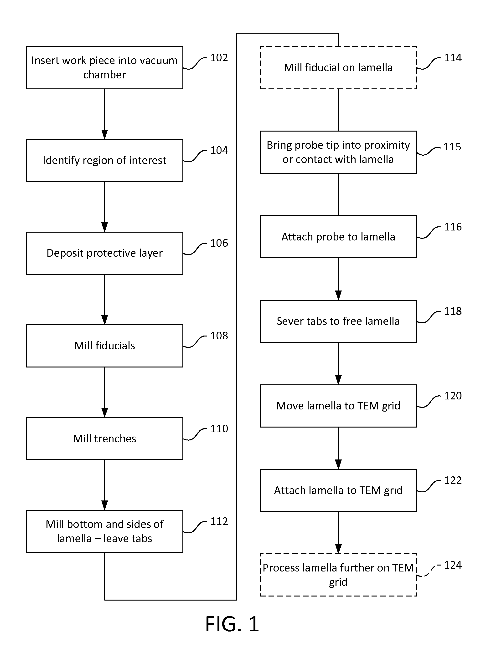
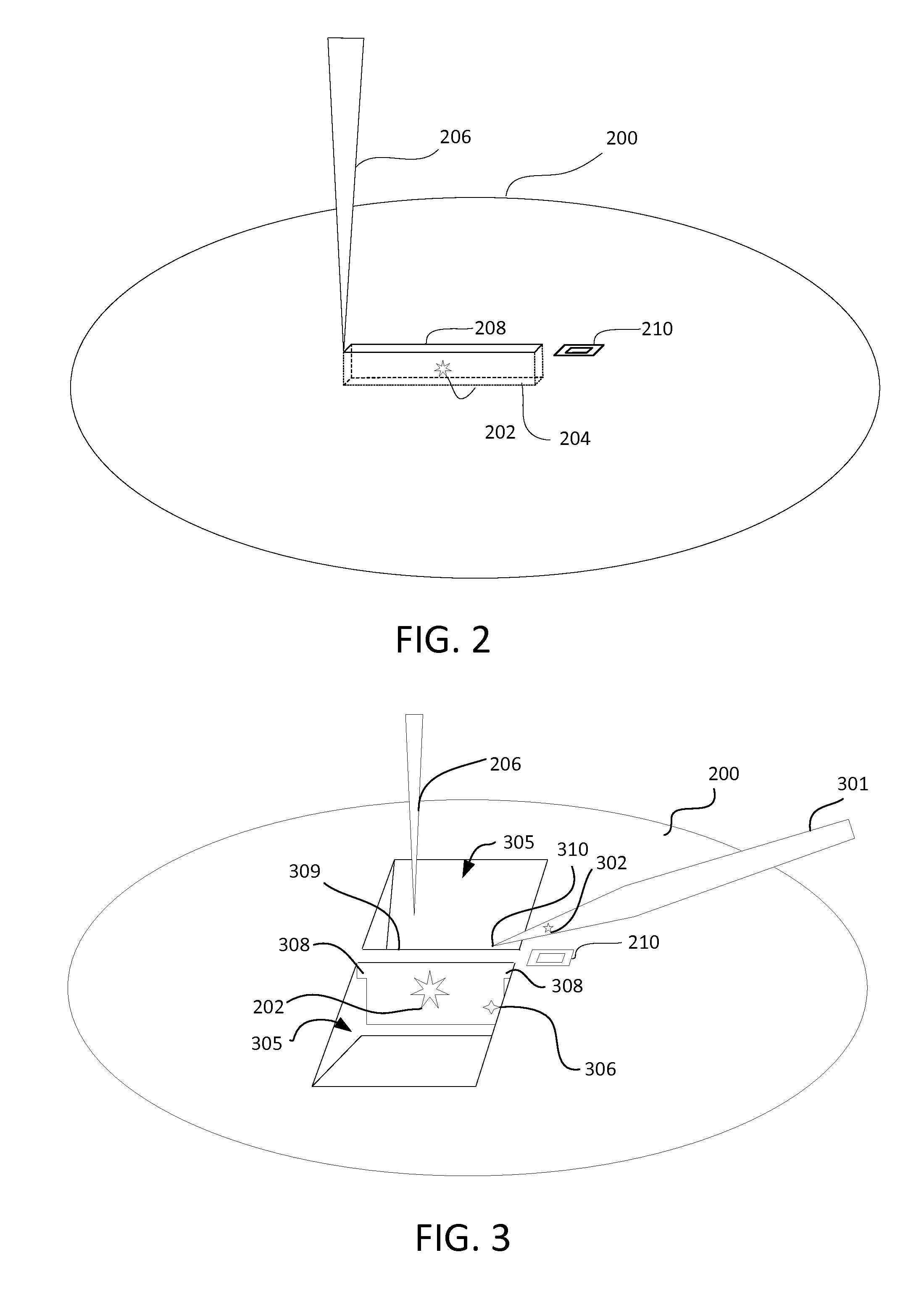
[0048]Preferred embodiments of the present invention are directed to various aspects of the production of thin lamellae for TEM analysis, including their extraction, transport, and subsequent attachment of the lamella to a sample grid for analysis by a fully or partly automated procedure.

[0049]The methods described below increase reliability to facilitate automation of each step in the lamella production and preparation.

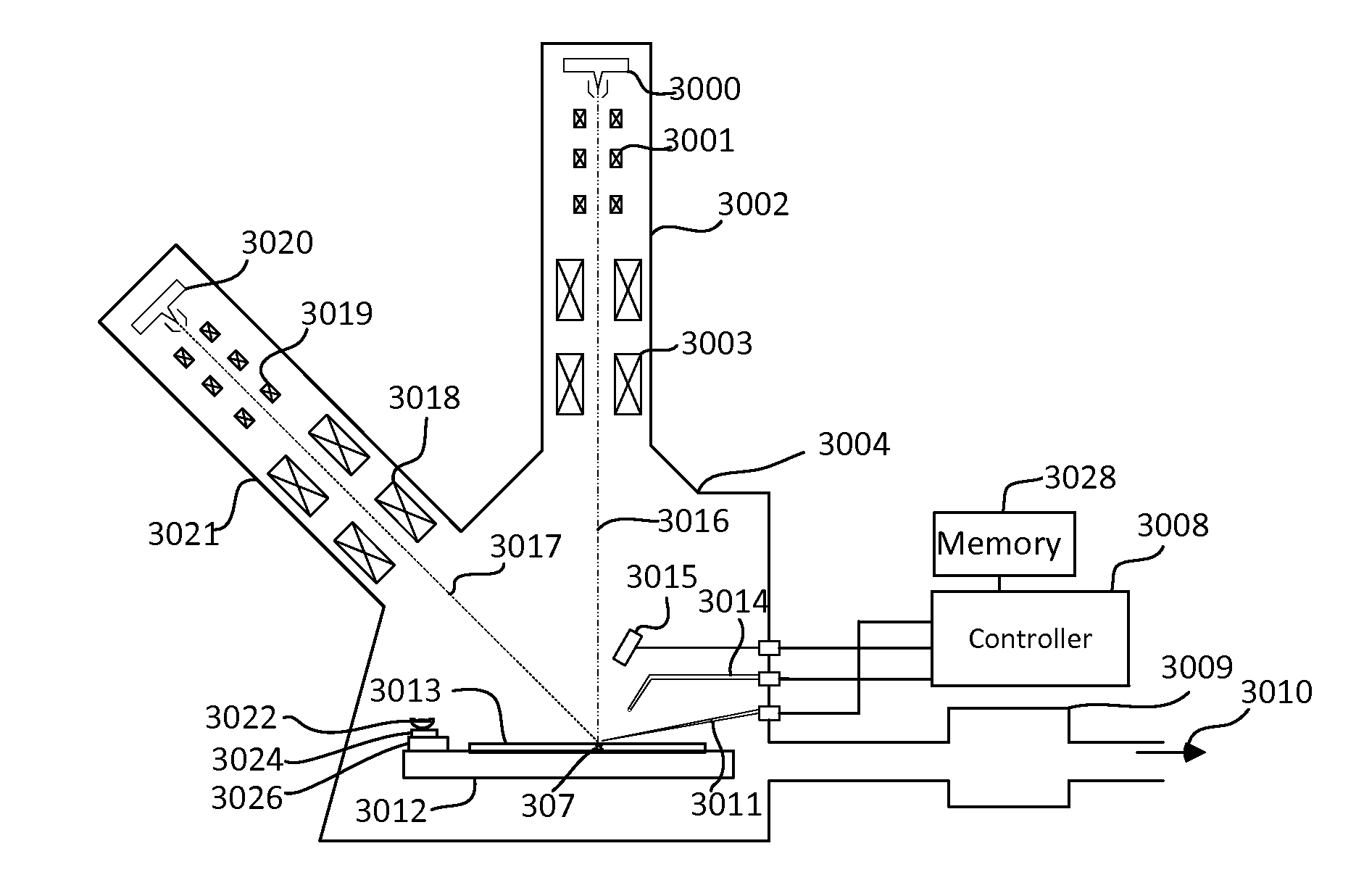
[0050]Some embodiments of the present invention use a dual-beam charged particle system, with a scanning electron microscope (SEM) and a focused ion beam system (FIB) combined to process a sample in a vacuum chamber. The electron beam can produce a high resolution image, while the ion beam can mill the sample to form the lamella. The ion beam is also used for imaging, although the ion beam damages the work piece during imaging. The two beams allow images to be formed from two different perspectives, allowing the position of an object in three dimensional space to be ...


PUM


Abstract

Techniques are described that facilitate automated extraction of lamellae and attaching the lamellae to sample grids for viewing on transmission electron microscopes. Some embodiments of the invention involve the use of machine vision to determine the positions of the lamella, the probe, and/or the TEM grid to guide the attachment of the probe to the lamella and the attachment of the lamella to the TEM grid. Techniques that facilitate the use of machine vision include shaping a probe tip so that its position can be readily recognized by image recognition software. Image subtraction techniques can be used to determine the position of the lamellae attached to the probe for moving the lamella to the TEM grid for attachment. In some embodiments, reference structures are milled on the probe or on the lamella to facilitate image recognition.

Description

[0001]This Application claims priority from U.S. Provisional Application 62 / 077,148, filed Nov. 7, 2014, which is hereby incorporated by reference.TECHNICAL FIELD OF THE INVENTION[0002]The present invention relates to automated preparation of samples for viewing in charged particle beam systems.BACKGROUND OF THE INVENTION[0003]Semiconductor circuit fabrication methods, as well as other microscopic and nanoscopic manufacturing techniques, have required the development of new imaging techniques, having improved resolution. Improved imaging techniques are also needed in the life sciences. Charged particle beam microscopy, such as electron microscopy and ion microscopy, provides significantly higher resolution and greater depth of focus than optical microscopy. In a scanning electron microscope (SEM), a primary electron beam is focused to a fine spot that scans the surface to be observed. Secondary electrons are emitted from the surface as it is impacted by the primary electron beam. Th...

Claims


Application Information

Patent Timeline
IPC IPC(8): H01J37/302H01J37/28H01J37/31H01J37/285
CPCH01J37/3023H01J37/285H01J2237/31745H01J37/31H01J37/28H01J37/3045H01J2237/208G01N1/286G01N2001/2873
Inventor BROGDEN, VALERIEBLACKWOOD, JEFFREYSCHMIDT, MICHAELTRIVEDI, DHRUTIYOUNG, RICHARD J.MILLER, THOMAS G.ROUTH, JR., BRIAN ROBERTSSTONE, STACEYTEMPLETON, TODD
Owner FEI CO
Why Eureka
Try Eureka