Potential of Zero charge-Based Capacitive Deionization

a capacitive deionization and zero charge technology, applied in the direction of centrifuges, separation processes, filtration separation, etc., can solve the problems of difficult separation of salt content by conventional filtration methods, high energy consumption of methods, and many other dissolved ionic compounds, so as to achieve the effect of fine adjustment of deionization

Active Publication Date: 2016-06-16
UNIV OF KENTUCKY RES FOUND
View PDF0 Cites 7 Cited by
  • Summary
  • Abstract
  • Description
  • Claims
  • Application Information

AI Technical Summary

Benefits of technology

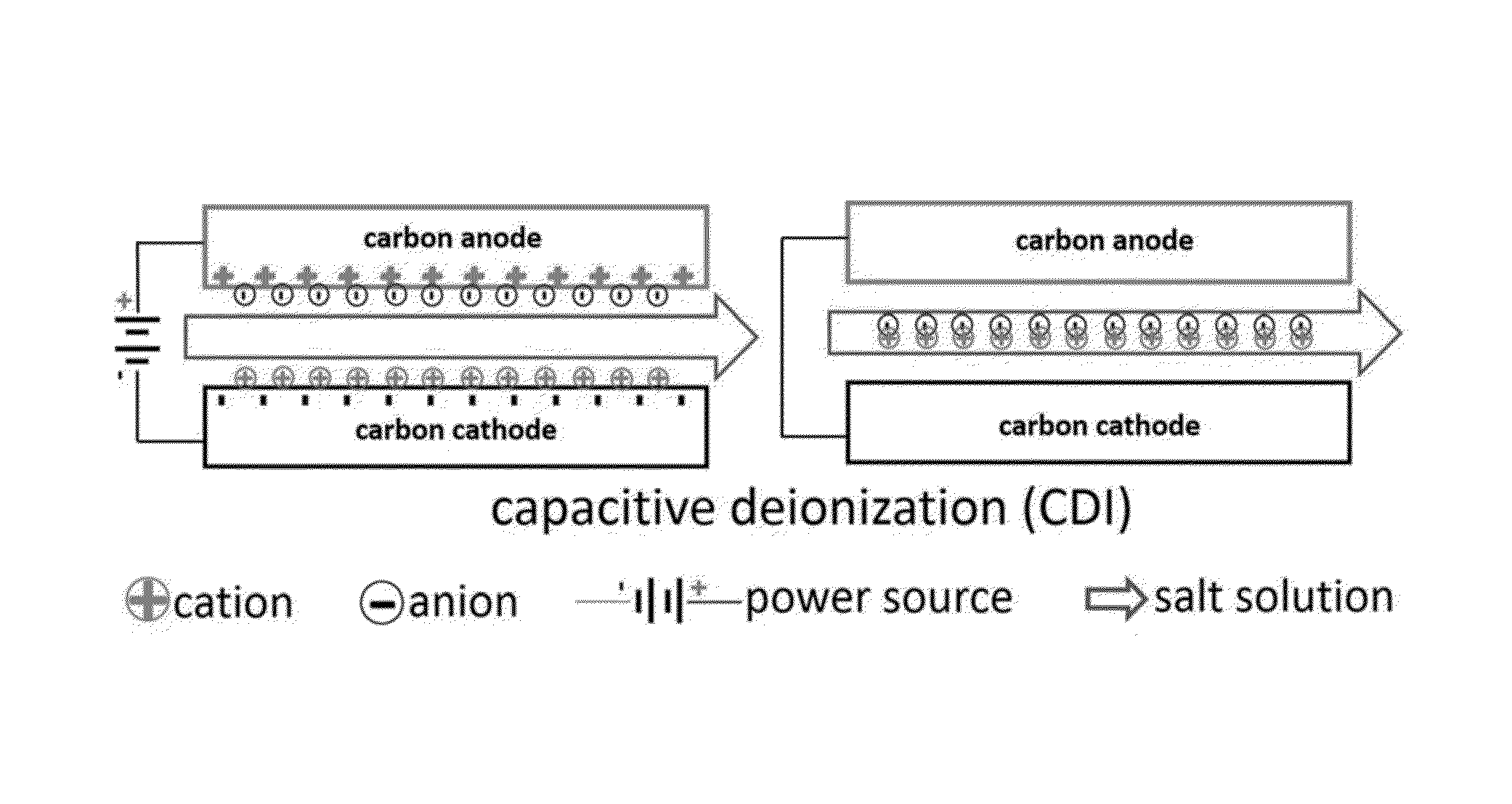
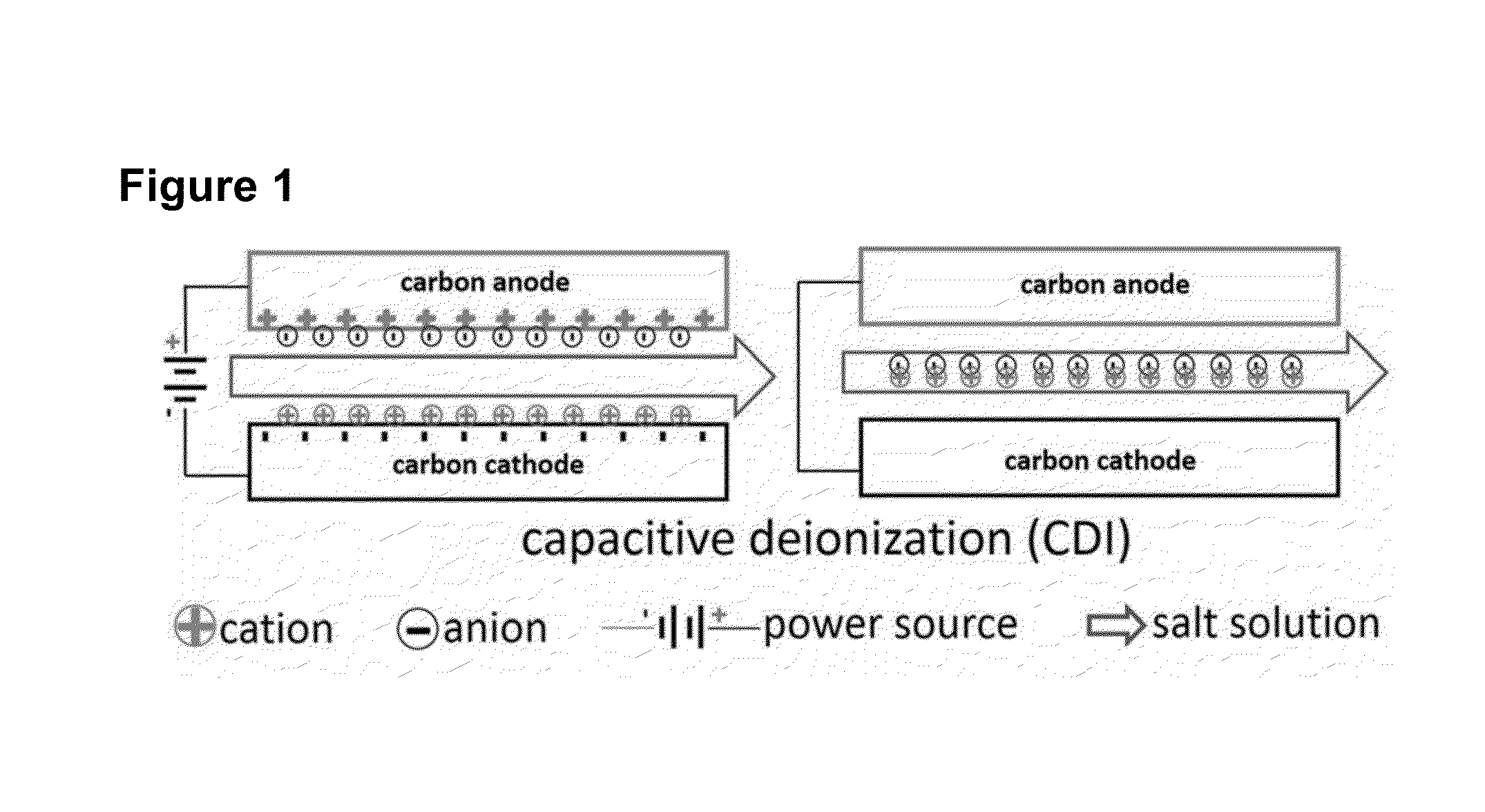
[0062]In all embodiments, anodes, cathodes, and ionic solution are contained in a structure with an inlet through which the solution (input stream) is admitted and permitted to contact the anode(s) and cathode(s), penetrations of electrical conductors through the structure to permit operation of a short circuit switch connected to the anode(s) and cathode(s) or application of user selectable voltage to the anode(s) and cathode(s), and an outlet in the structure through which deionized solution (output stream) or solution with desorbed ions (waste stream) is discharged from the structure. The structure is typically closed except for the inlet, outlet, and penetrations of electrical conductors to effect short-circuiting of, or application of voltage to, the anode(s) and cathode(s). The structure and its contents are called a deionization cell. In alternate embodiments, the switch and an internal power supply can be wirelessly controlled to avoid penetration of the structure by electrical conductors.
[0063]The degree of purification (deionization) of an input stream is controlled primarily by the total electrode surface area in a cell to which a given volume of input stream is exposed, the duration of exposure for adsorption of ions before desorption, the voltage (potentials) or current modulated in the system, and the working voltage window (described below). Controlling the degree of purification (deionization) through modulation of the current supplied or drawn from the deionization cell, or through modulation of voltage supplied or drawn from the deionization cell, enables fine adjustment of deionization.

Problems solved by technology

Salt content is difficult to separate by conventional filtration methods due to the small molecular size of most salts.
Many other dissolved ionic compounds are also challenging to separate via typical chemical precipitation routes.
While effective, this method is quite energy intensive and suffers from equipment corrosion issues.
While RO is typically more efficient than MSF, it requires pumps capable of higher pressures and is subject to organic, biological, and precipitation-based fouling of the membrane surface, which ultimately limits the lifetime of the separation process and increases the expense, especially at municipal scale.
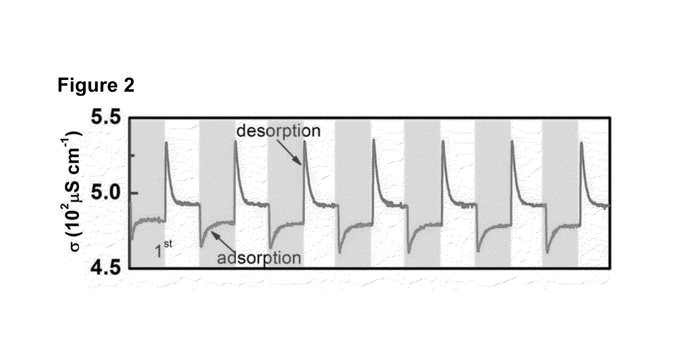
When the cell potential is reduced, short-circuited, or removed, the driving force for ion adsorption is subsequently reduced at the carbon surface, resulting in ion desorption.
While this process sounds relatively simple, in actuality, the separation process is more complex, e.g., changing surface electrode properties substantially changes the salt separation process.
This means that the CDI cell is no longer functioning as a salt separation device: it has reached the end of device life and must be replaced.
Shown in FIG. 5 is a loss in the charge efficiency as the salt adsorption capacity decreases to zero.
In an automotive analogy, a CDI cell gets terrible gas mileage and is not economically acceptable.
If a CDI cell were implemented with a current CDI cell lifetime of 10 days, and if each CDI cell costs $5000, the 2-year cell replacement cost would be $365,000, reflecting cell replacement every 10 days (but excluding labor and administrative costs), an obviously unacceptable value.
Research in carbon electrodes has focused on the improving the porosity of carbon materials with which to construct supercapacitor electrodes, but research has not been conducted that would be particularly relevant to ionic separation and water purification.
However, the addition of membranes to the conventional CDI cell increases overall cell cost dramatically, making commercial success at a large-scale much more difficult, and does not address the underlying cumulative (aggregate cycle dependent) degradation process (i.e., short cell life, aka deactivation) for a conventional CDI cell shown in FIG. 4.

Method used


Image

  • Potential of Zero charge-Based Capacitive Deionization
  • Potential of Zero charge-Based Capacitive Deionization
  • Potential of Zero charge-Based Capacitive Deionization

Examples


Embodiment Construction

[0108]Shown in FIG. 6 is a cyclic voltammogram (CV) of a pristine carbon xerogel electrode in N2 deaerated 4.3 mM NaCl solution with a scan rate of 1 mV / s. CVs differ from linear sweep voltammetry in that after the set potential is reached in a CV experiment, the working electrode's potential is ramped in the opposite direction to return to the initial potential. The current at the working electrode is plotted versus the applied voltage (i.e., the working electrode's potential) to give the cyclic voltammogram trace. The CV trace is typically a hysteresis, even for perfectly reversible mechanisms. Even reversible couples contain polarization overpotential and thus display a hysteresis trace when potential is ramped up from negative to positive and then ramped down from positive to negative, passing through an initial potential. This overpotential emerges from a combination of analyte (e.g., ion) diffusion rates and the intrinsic activation barrier of transferring electrons from the e...


PUM

PropertyMeasurementUnit
working voltageaaaaaaaaaa
flow rateaaaaaaaaaa
chargeaaaaaaaaaa

Abstract

The invention is a capacitive, aka electrostatic, deionization apparatus and method that solves the problem of short lifetime of conventional capacitive deionization (CDI) and of membrane capacitive deionization (MCDI) devices and methods by shifting the Potential of Zero Charge of electrode surfaces through surface modifications. Such electrode surface modifications provide very long lifetime capacitive deionization devices and methods.

Description

RELATED APPLICATIONS[0001]This application claims the benefit under 37 CFR 1.78 of U.S. provisional patent application No. 62 / 086,857, filed 3 Dec. 2014, and U.S. provisional patent application No. 62 / 195,578, filed 22 Jul. 2015.FEDERAL FUNDING AND JOINT RESEARCH AGREEMENT[0002]The research leading to the invention disclosed herein was partially funded by U.S. Dept. of Energy contract no. DE-PI0000017, which contract provides partial funding for a Joint Research Agreement among the University of Kentucky, West Virginia University Research Corporation, Huazhong University of Science and Technology, and 26 additional parties listed at http: / / www.us-china-cerc.org / Advanced_Coal_Technology.html.BACKGROUND OF THE INVENTIONField of the Invention[0003]The field of the invention is capacitive, aka electrostatic, deionization devices and methods used to remove salt and other ions from solutions.DEFINITIONS[0004]“Adsorption” means attracting ions in an input stream to, and retaining those ion...

Claims


Application Information

Patent Timeline
Patent Type & Authority Applications(United States)
IPC IPC(8): C02F1/469
CPCC02F2201/46C02F1/4691C02F2001/46138C02F2209/05C02F2001/46133
Inventor GAO, XINOMOSEBI, AYOKUNLELANDON, JAMES RICHARDSONLIU, KUNLEI
Owner UNIV OF KENTUCKY RES FOUND
Why Eureka
Try Eureka