Braided Self-Expanding Endoluminal Stent and Manufacturing Method Thereof

a self-expanding, endoluminal technology, applied in the field of medical instruments, can solve the problems of sudden limb pain, sudden limb pain, skin temperature drop, etc., and achieve the effects of reducing shortening, accurate positioning, and easy control

Active Publication Date: 2016-07-28
LIFETECH SCIENTIFIC (SHENZHEN) CO LTD
View PDF19 Cites 9 Cited by
  • Summary
  • Abstract
  • Description
  • Claims
  • Application Information

AI Technical Summary

Benefits of technology

[0031]Compared with the prior art, the present invention has the following advantages. The braided self-expandable endoluminal stent provided by the present invention uses axial wave bands and inherits the advantages of closed-loop braided endoluminal stents. For example, repeatedly positioning may be realized, that is, the stent may be withdrawn into the sheath after partially released, then to be released again after position adjustment. On the other hand, the shortening is reduced so that the stent is unlikely to experience displacement during the release process; as a result the positioning is accurate and easily controlled. Furthermore, both the flexibility and the axial strength are improved, so that the stent may bear a large bending angle without kinking or losing the radial support force. Thus, the stent may be implanted into various tortuous diseased parts of the human vasculature. The fixed cross-linking points are distributed on the circumference, thereby ensuring the radial support strength of the endoluminal stent; and crossing points are distributed in different crossing segments, thereby facilitating the improvement of the flexibility of the endoluminal stent. As the fixed cross-linking points are distributed on the boundary of the adjacent crossing segments, the crossing points alternate to the fixed cross-linking points, and there are more crossing points than fixed cross-linking points, the density of the grid is enhanced and the stability of the structure is therefore better. The coverage to the artery atherosclerotic plaque is increased, the tubular grid is allowed to be deformed appropriately, the stress and the friction force are dispersed evenly, and the shortening, the flexibility and the radial support strength are balanced.

Problems solved by technology

Renal arterial stenosis is likely to result in renal arterial dysfunction.
Sudden onset of lower limb arterial occlusion will result in sudden limb pain, skin temperature drop, skin color change, pale skin, and even limb amputation if severe; and lower limb arterial stenosis is usually followed by weakness, numbness, cold of limb, and intermittent limb pain after activities.
For patients suffering from slight arterial stenosis or patients having no clinical symptoms, medical drug therapy may be adopted which, however, does not work for patients with severe symptoms.
However, surgical operation causes big injuries and has many complications.
Arterial thrombolysis and thrombectomy are applicable to acute iliofemoral artery thrombus or embolism patients, however, are not applicable to chronic vessel stenosis or occlusion lesions.
In spite of good effects in the short term, balloon percutaneous transluminal angioplasty has a high incidence of complications mainly including plaque or detachment of thrombus which causes embolism of distal vessels.
Additionally, the incidence of vessel restenosis after angioplasty is high.
Such a stent, although accurate in positioning due to small axial shortening after expansion, is poor in its flexibility and thus is just applicable to be placed in a flat vessel; furthermore, the incidence of restenosis is higher than for self-expanding stents.
Self-expanding endoluminal stents manufactured in this way are not applicable to be bent in human endoluminal positions having activities to some extent, due to their poor flexibility and high occurrence of fatigue fracture.
However, the braided self-expandable endoluminal stents in the prior art are quite high in axial shortening; that is, after an endoluminal stent previously compressed in the sheath is released from the sheath, the length of the endoluminal stent after it automatically expands is significantly shortened.
Such shortening will result in difficulties in the positioning and control of the stent during the release process; and, the radial support force of the stent is reduced and the stent is likely to experience displacement.

Method used


Image

  • Braided Self-Expanding Endoluminal Stent and Manufacturing Method Thereof
  • Braided Self-Expanding Endoluminal Stent and Manufacturing Method Thereof
  • Braided Self-Expanding Endoluminal Stent and Manufacturing Method Thereof

Examples


first embodiment

The First Embodiment

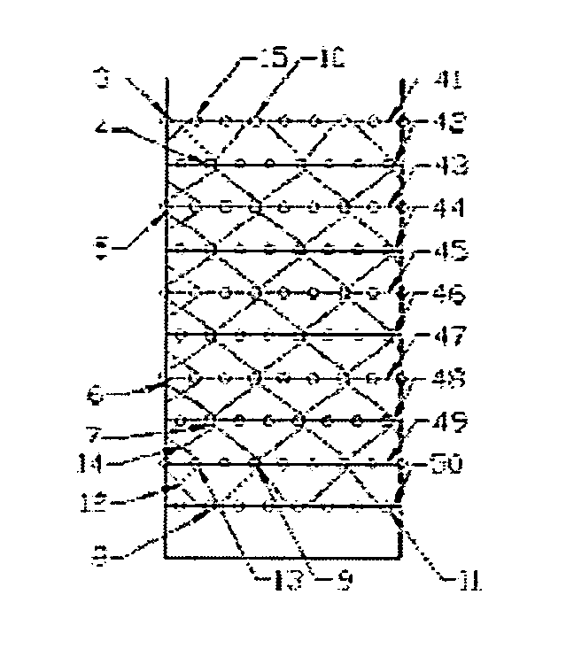
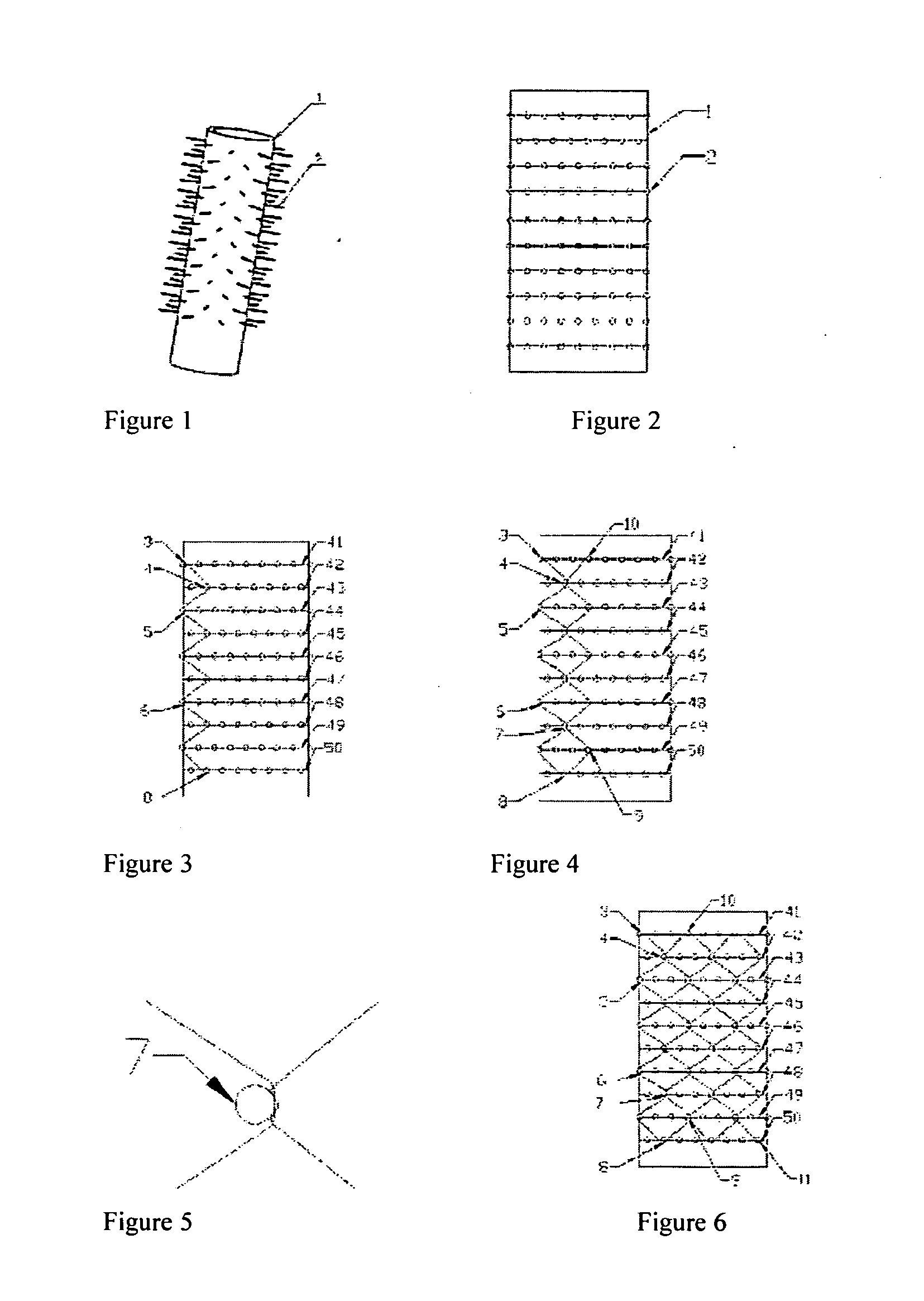
[0061]FIG. 1 shows a pin jig required for manufacturing this endoluminal stent. This pin jig comprises a mandrel 1 with round holes and pins 2 inserted into the round holes. On the mandrell, there are eight round holes in each circle along the circumferential direction of the side wall, the azimuth angle of round holes on two adjacent circumferences are staggered, and each of the pins 2 is fixed into one round hole of the mandrel 1, respectively. FIG. 2 is a schematic diagram of the mandrel 1 of FIG. 1, with the lateral surface thereof unfolded into a plane. The pins 2 are distributed evenly along the circumferences, and each of the circumferences is unfolded into a straight line. This mandrel has a total of ten circumferences in the axial direction and the distances between the adjacent circumferences are the same. Although this mandrel has ten circumferences, depending upon demands, the number of circumferences on the mandrel may be reduced to four. There may a...

second embodiment

The Second Embodiment

[0068]FIG. 10 is a schematic diagram of a mandrel for manufacturing this stent, with the lateral surface unfolded into a plane, where n=3 and k=3. Different from FIG. 2, the pins 2 on the mandrel are arrayed on eight circumferences, respectively, with eight pins 2 on each of the circumferences, and the pins 2 respectively on two adjacent circumferences are staggered. The spacing between the first circumference 51 and the second circumference 52 at one end is equal to that between the seventh circumference 57 and the eighth circumference 58 at the other end, and the axial distance between two adjacent circumferences of the rest circumferences is twice of that between two adjacent circumferences at either end. For example, the distance between the second circumference 52 and the third circumference 53, the distance between the fourth circumference 54 and the fifth circumference 55, and the distance between the sixth circumference 56 and the seventh circumference 5...

third embodiment

The Third Embodiment

[0075]FIG. 17 is a schematic diagram of a mandrel for manufacturing an endoluminal stent of this embodiment, with the lateral surface unfolded. This mandrel differs from the mandrel of the first embodiment in that this mandrel includes two cylindrical segments having different diameters, i.e., a small cylindrical segment 29 having a smaller diameter and a large cylindrical segment 31 having a larger diameter, which are connected to each other by a tapered segment 30 to form a mandrel with three segments as a whole. To manufacture various endoluminal stents or support members of different shapes, the shape of this mandrel may vary, for example, a multi-segment structure having an outer diameter varying like a trapezoid, a structure having a bell mouth at one or two ends, and a continuously tapered structure. By the method of braiding in segments, various endoluminal stents or support members with corresponding shapes are manufactured.

[0076]In this embodiment, the ...


PUM


Abstract

A braided self-expandable endoluminal stent comprises a tubular grid formed by connection of a plurality of wave bends in the circumferential direction. Each of the wave bands comprises a plurality of crests and troughs of an elastic wire in the axial direction, and is respectively connected with another wave band. On two sides of each of the wave bands, there is a wave band abutted thereto side by side. There is at least one cross-linking point between every two wave bands abutted side by side. Each of the cross-linking points is formed by intersecting one trough on one of the wave bands abutted side by side with one corresponding crest on the other wave band, and at least one part of the cross-linking points are fixed cross-linking points. Each of the wave bands is further staggered and overlapped with at least another wave band, and a plurality of crossing points (12, 14, 22, 23) are formed between the wave bands which are staggered and overlapped with each other. Each of the wave bands, together with at least another wave band, forms a group of parallel wave bands. As the wave bands in this group are similar in wave shape and in parallel to each other, no cross-linking points or crossing points (12, 14, 22, 23) will be formed between the parallel wave bands.

Description

TECHNICAL FIELD[0001]The present invention relates to a medical instrument for supporting or repairing human vessels, in particular to a braided self-expanding endoluminal stent for endoluminal interventional treatment of arterial stenosis or occlusion and a manufacturing method thereof.BACKGROUND OF THE INVENTION[0002]Human vessels includes arteries, veins, tracheae, bronchi, esophagi, bile ducts, urethras, etc, the diameters of which vary from several millimeters to a few tenths of millimeters. Those human vessels may have various diseases, for example, collapse, occlusion and damage, and corresponding endoluminal stents may be used for treating those endoluminal diseases. Those endoluminal stents should satisfy some common requirements. For example, they may be encapsulated into tiny sheathes, delivered into human vessels and then released, expanded and then supported at the predetermined endoluminal positions, for the purpose of treatment.[0003]As arteries are more likely to hav...

Claims


Application Information

Patent Timeline
Patent Type & Authority Applications(United States)
IPC IPC(8): A61F2/89D04C1/06A61F2/86
CPCA61F2/89A61F2/86A61F2240/001A61F2230/0069D04C1/06A61F2/90A61F2250/001D10B2509/06D04C3/48
Inventor WANG, YONGSHENG
Owner LIFETECH SCIENTIFIC (SHENZHEN) CO LTD
Why Eureka
Try Eureka