Gas recovery concentration apparatus

Active Publication Date: 2016-09-22
SEIBU GIKEN CO LTD
View PDF0 Cites 25 Cited by
  • Summary
  • Abstract
  • Description
  • Claims
  • Application Information

AI Technical Summary

Benefits of technology

[0054]A pre-cooling zone and a preheating zone are provided as stated above, the circuit which circulates through each is constituted, and it has the advantage that the amount of cooling energies and the heating amount of energy for desorption are simultaneously reducible by circulating gas.
[0055]In view of a field of carbon dioxide recovery concentration efficiency, since the desorption zone contains high-concentration carbon dioxide gas which has a high temperature, the carbon dioxide which is stuck to an adsorption material remains without being completely desorbed. Since low-concentration carbon dioxide gas as compared with the desorption zone passes when the rotor moves to a pre-cooling zone and the honeycomb still has heat storage at high temperatures, there is an advantage that desorption of the carbon dioxide which remained is promoted.
[0056]The gas passed through the pre-cooling zone is added by the carbon dioxide desorbed during passage, becomes higher than the carbon dioxide levels of material gas, and is introduced into a preheating zone. The honeycomb wh

Problems solved by technology

However, the coal has a problem that the coal emits a carbon dioxide and a sulfide much at the time of combustion of the coal as compared with oil or natural gas.
Not only coal but also heavy oil has the same problem as the coal has.
However, even if SOx and nitrogen oxide were removed and it prevented environmental pollution, carbon dioxide was still emitted so much and there remains a problem of promoting global warming.
Therefore, energy expenditure becomes excessive.
However, an expensive corrosion-resistant material is required for dealing with alkaline fluid, and it costs high.
Although the heat exchanger was used for the key devices and energy saving of a whole system has been attained, since the calorific capacity of the fluid to be used is large, the limit of the energy saving is approached.
(Non-patent literature 2) Further

Method used


Image

  • Gas recovery concentration apparatus
  • Gas recovery concentration apparatus
  • Gas recovery concentration apparatus

Examples


embodiment 1

Preferred Embodiment 1

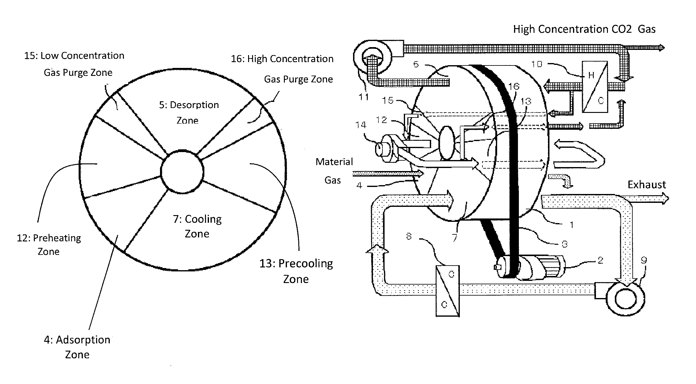
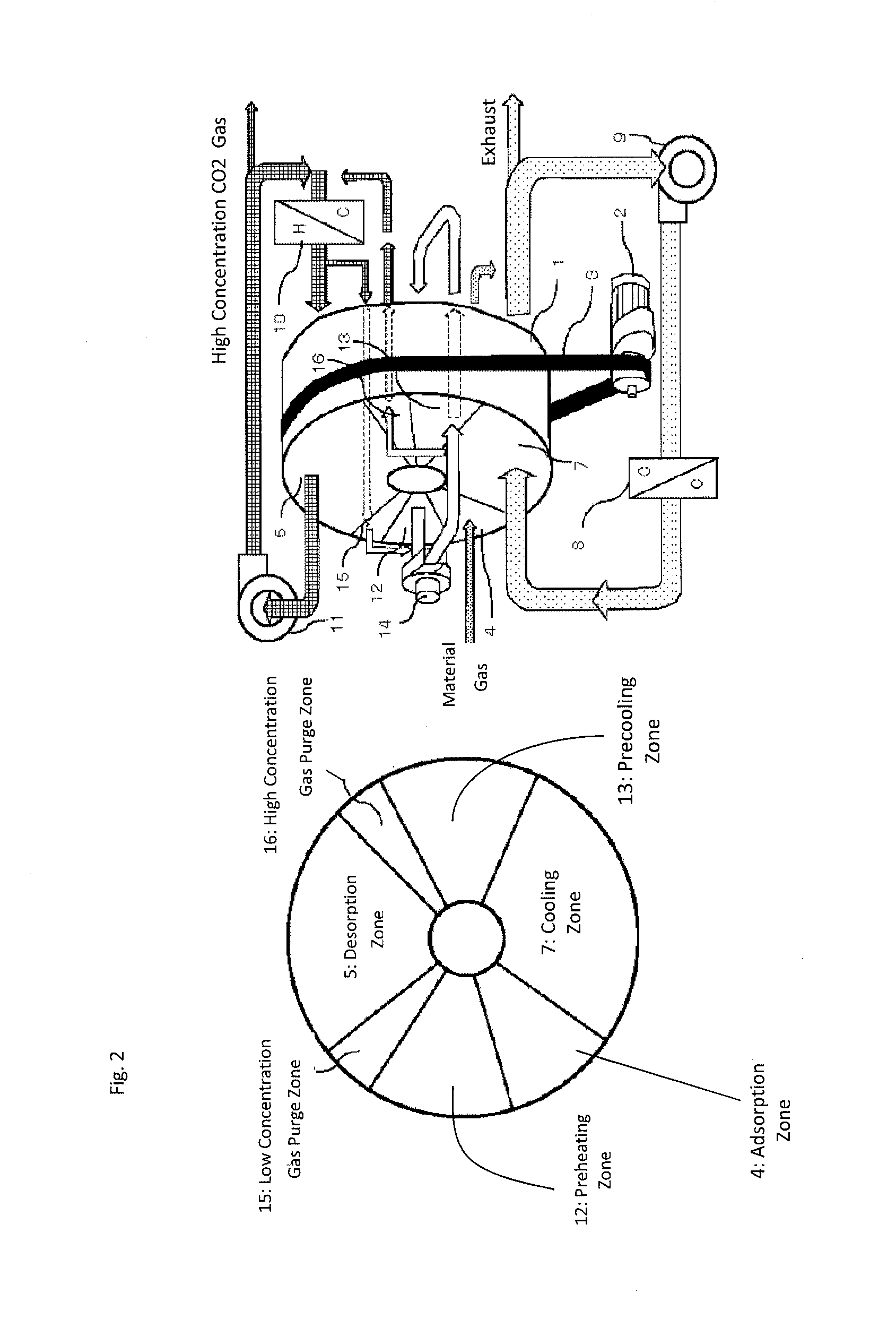
[0098]The preferred embodiment 1 is shown in FIG. 2. The same number is attached to the same structure as the construct of the conventional embodiment in FIG. 1.

[0099]The embodiment 1 is constituted so that a carbon dioxide recovery concentration apparatus returns to the adsorption zone 4 through the adsorption zone 4, a preheating zone 12, a low concentration gas purge zone 15, a heating desorption zone 5, a high concentration gas purge zone 16, a pre-cooling zone 13, a cooling zone 7 in turn along with a rotating direction of the carbon dioxide recovery concentration rotor.

[0100]It is the same as a conventional embodiment that material gas is merged and mixed in a coolant gas circulation circuit after passing through the adsorption zone 4, the gas is cooled by the gas cooling coil 8, circulates in the circuit to cool the honeycomb of cooling zone 7, and a part of the gas is exhausted.

[0101]The desorption gas constitutes the circulation circuit by a desorption...

embodiment 2

Preferred Embodiment 2

[0114]The preferred embodiment 2 is shown in FIG. 3. In the embodiment 1, the high concentration gas in the desorption circuit introduced into the low concentration gas purge zone 15, and the gas purged in the high concentration gas purge zone 16 is returned to the desorption circuit. However, the preferred embodiment 2 has a flow which does not relate to the desorption circuit. The high concentration gas purge zones 16 is purged by using a part of gas of pre-cooling zone 13, the recovered high concentration gas is introduced into low concentration gas purge zone 15, and the purged gas is made to return to an exit of the pre-cooling zone 12. Although the effect of a gas purge is the same, it is not subject to the influence of desorption circuit pressure.

embodiment 3

Preferred Embodiment 3

[0115]The preferred embodiment 3 is shown in FIG. 4. As the difference from the embodiments 1 and 2, the embodiment 3 constitutes the closed circulation circuit by the low concentration gas purge zone 15 and the high concentration gas purge zone 16, and the gas is made to circulate in purge gas circulation Blois 17. Since the low concentration gas purge zone 15 and the high concentration gas purge zone 16 constitute a circulation route, both of them are not subject to the influence of the pressure of other zones.

[0116]In the above embodiments 1-3, the embodiments are explained by using the carbon dioxide gas which is acidic gas. However, the proposal is not limited to the carbon dioxide gas, and is applicable to other acidic gases, alkaline gas, etc. by changing suitably adsorbent such as zeolite supported on an adsorption honeycomb rotor, activated carbon, silica gel, meso-porous silica, alumina, ion-exchange resin, argillite, and an inorganic compound.

[0117]T...


PUM

PropertyMeasurementUnit
Concentrationaaaaaaaaaa
Adsorption entropyaaaaaaaaaa

Abstract

In the honeycomb rotor recovery concentration apparatus which collects gas, such as carbon dioxide, from stack gas etc., it collects by the highest possible recovery rate, and condenses to the highest possible concentration, and lessens the amount of energy for recovery concentration as much as possible. Adsorption zone 4, preheating zone 12, low concentration gas purge zone 15, desorption zone 5, high concentration gas purge zone 16, pre-cooling zone 13, and cooling zone 7 are provided to the hand of cut of a rotor. Low concentration gas is prevented from mixing in desorption zone 5, and high concentration gas is prevented from being spilt out from desorption zone 5. Pre-heating zone 12 and pre-cooling zone 13 constitute a circulation circuit, and it raises energy-saving nature by pre-cooling and carrying out preheating heat exchange by gas which circulates through a circuit.

Description

CROSS-REFERENCE TO RELATED APPLICATIONS[0001]This application claims the benefit of Japanese Patent Application No. 2015-057045, filed Mar. 20, 2015, in the Japanese Patent Office, the disclosure of which is incorporated herein by reference.BACKGROUND[0002]1. Field[0003]The present invention relates to a thermal swing carbon dioxide recovery concentration apparatus which collects carbon dioxide by a high recovery rate and condenses the carbon dioxide to high concentration with little consumption energy.[0004]2. Description of the Related Art[0005]The effort and trail to reduce carbon dioxide emitted from industry, a car and a home as much as possible as counterplan against global warming is carried out on the world level. For example, the apparatus which consumes energy is improved to become an energy saving type and the old apparatus is replaced by the improved apparatus. As apparatus which produces energies such as power generation, etc., some technologies using renewable energy s...

Claims


Application Information

Patent Timeline
IPC IPC(8): B01D53/06C01B32/50
CPCB01D53/06B01D2253/3425B01D2257/504B01D53/0438B01D53/62B01D53/83B01D2253/108Y02C20/40
Inventor OKANO, HIROSHI
Owner SEIBU GIKEN CO LTD
Why Eureka
Try Eureka