A guard structure for signal isolation

Active Publication Date: 2016-10-06
THALES SOLUTIONS ASIA +2
View PDF7 Cites 25 Cited by
  • Summary
  • Abstract
  • Description
  • Claims
  • Application Information

AI Technical Summary

Benefits of technology

[0071]In one embodiment, the plurality of thread-like structures are synthesized on one or more electrically conductive portions (such as on via-fenced guard traces) on the mounting surface of the substrate. Preferably, the one or more electrically conductive portions are coupled to a ground plane on a surface of the substrate opposite to the mounting surface by providing a plurality of vias extending through the substrate. In this way, the wall-like structures can be regarded as an upward extension of the via-fenced guard trace in the vertical direction. Advantageously, the integration between wall-like structures together with the via-fence

Problems solved by technology

Although the via-fencing technique is known to be effective in RF isolation, its use is limited to packages or ICs without space constraints.
Therefore, this solution has limitations for designs with limited real estate and/or tightly coupled mixed-signal traces or ICs in close proximity.
This problem becomes even more prominent in high speed applications and/or high density circuitries.
However, to date such metallic walls can only be built separately by casting or molding [5].
Existing surface micromachining techniques used in microelectronic processes are generally not available to build such metallic walls because those techniques usually have very limited build-up thickness for metals.
For example, solid metallic walls structures with a high aspect ratio (i.e. height/thickness of the wall), such as metal pillars having an aspect ratio greater than two, are not achievable by existing surface micromachining techniques used in microelectronics p

Method used


Image

  • A guard structure for signal isolation
  • A guard structure for signal isolation
  • A guard structure for signal isolation

Examples


Example

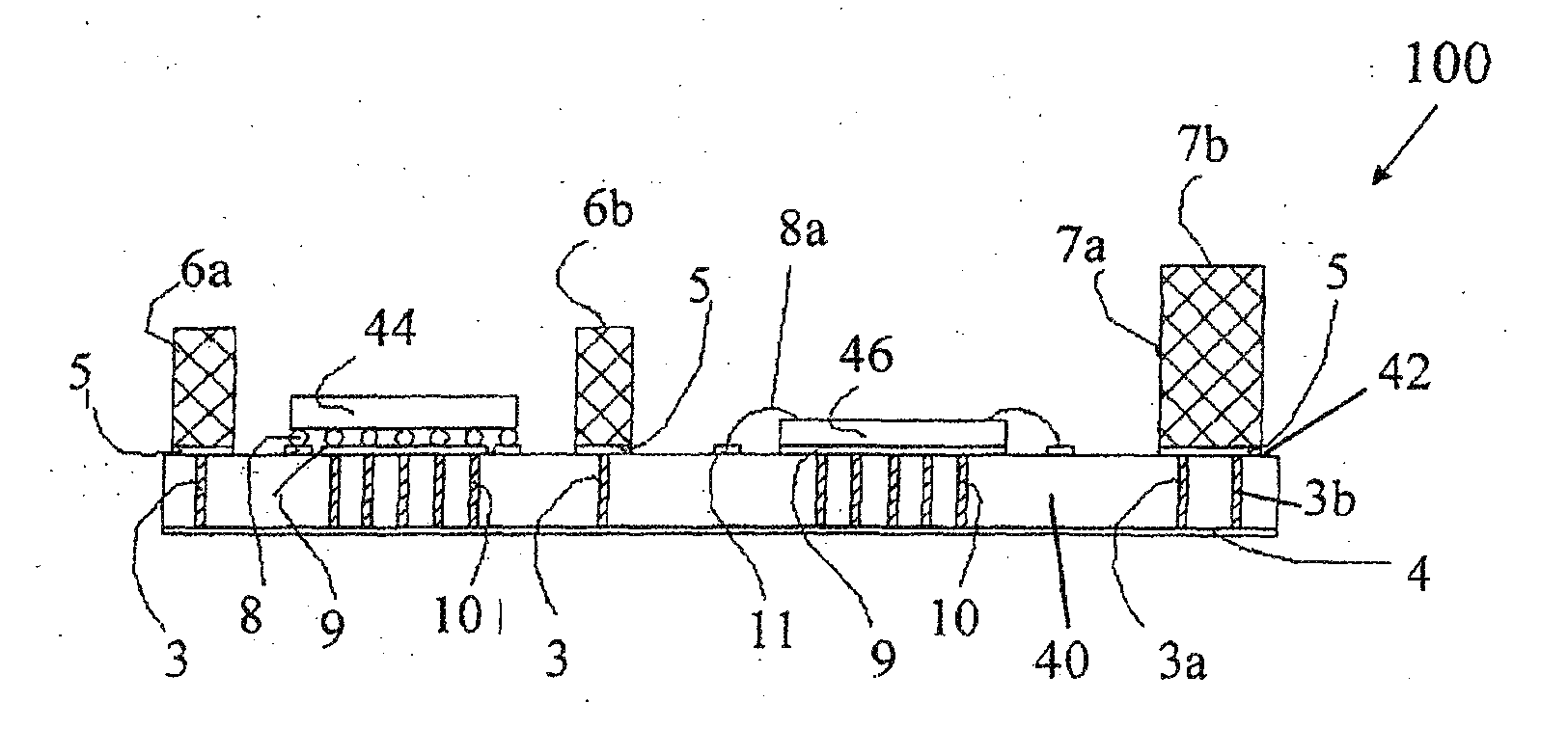
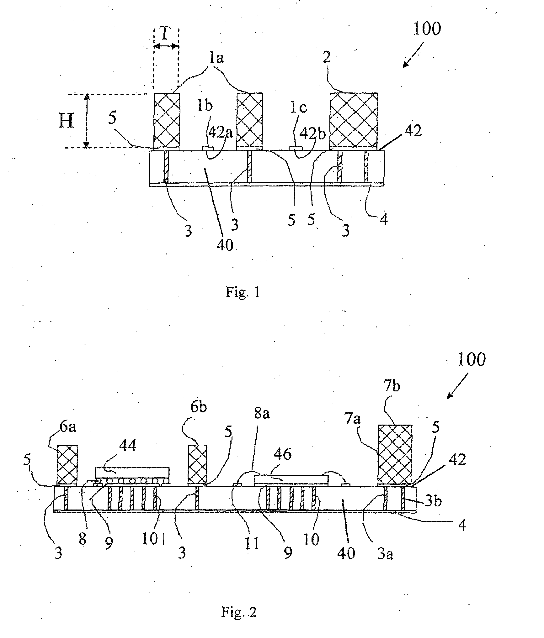
[0104]FIG. 1 shows a support structure 100 for providing signal isolation between signal traces 1b, 1c. The support structure 100 has a substrate 40 having a mounting surface 42 comprising first areas 42a, 42b for hosting the signal traces 1b, 1c. In this example, the substrate is a piece of silicon wafer. The mounting surface 42 has one or more electrically conductive portions 5 coupled to a ground plane 4. The support structure 100 further includes a plurality of thread-like structures synthesized on the electrically conductive portions. The plurality of thread-like structures collectively define electrically conductive projections 1a, 2 upstanding from (i.e. extending transverse to) the mounting surface 42. In this example, the electrically conductive projections 1a, 2 form continuous wall-like structures that surround around the signal traces 1b, 1c. The walls are elongate parallel to the mounting surface. For example, it extends along with the length of the signal traces 1b, 1c...


PUM


Abstract

A method of fabricating an electrical guard structure for providing signal isolation is provided. The method includes providing a substrate having a mounting surface comprising a first area for hosting at least one electronic component. The method further comprises synthesizing a plurality of thread-like structures over the substrate to collectively form one or more electrically conductive projections extending transverse to the mounting surface. The one or more electrically conductive projections include one or more wall-like structures which are elongate parallel to the mounting surface. The electrically conductive projections can be transferred to another surface such as a major surface of a second substrate. There are further provided a support structure and a guard structure having the wall-like electrically conductive projections which are electrically grounded when in use to provide signal isolation.

Description

FIELD OF INVENTION[0001]This invention involves the implementation of an electrical guard structure for signal isolation in electronic circuitry such as integrated circuits (ICs), or between IC packages or other electronic components on a substrate such as a printed circuit board. The invention can be used in, but is not limited to, Microwave Monolithic Integrated Circuits (MMIC), Multiple Chip Module (MCM), System-in-Package (SiP), System-on-Package (SoP), and Integrated Circuit Electromagnetic Interference / Compatibility (IC EMI / EMC) solutions.BACKGROUND OF INVENTION[0002]The integration of digital and RF components in densely routed architectures requires careful layout design to ensure adequate DC or mixed-signal isolations in compliance with specifications for a particular application. To meet the emerging need to downscale complex multifunctional integrated circuit packages, layout routing techniques, packaging design and isolation methods have become very critical design consi...

Claims


Application Information

Patent Timeline
IPC IPC(8): H01L23/552H01L23/66H01L23/00H01L23/498H01L25/065
CPCH01L23/552H01L2924/01006H01L23/49838H01L25/0655H01L24/17H01L24/32H01L24/48H01L24/73H01L25/0657H01L23/66H01L2224/16227H01L2224/32165H01L2224/16235H01L2224/48091H01L2224/48106H01L2224/48227H01L2224/73265H01L2225/0651H01L2225/06517H01L2225/06548H01L2225/06572H01L2223/6683H01L2924/14H01L2924/1423H01L2924/1421H01L2924/3025H01L23/49827B82Y10/00H01L23/04H01L23/49877H01L24/16H01L25/0652H01L25/16H01L29/0676H01L29/413H01L2223/6616H01L2224/16225H01L2224/32225H01L2924/157H05K9/0022H01L23/3677H01L23/373H01L23/5384H01L23/5385H01L2924/00014H01L2924/00012H01L2224/0401H01L2224/45099H01L2224/45015H01L2924/207H01L2224/85399H01L2224/05599
Inventor TAN, DUNLINYU, JONG JENHEE, DAVIDTAY, BENG KANGBAILLARGEAT, DOMINIQUE
Owner THALES SOLUTIONS ASIA
Why Eureka
Try Eureka