Laser Systems And Related Methods

a laser system and laser technology, applied in the field of laser systems, can solve the problems of complex electronic systems, low pulse energy, and difficulty in synchronization, and achieve the effects of reducing amplified spontaneous emission, facilitating the generation of the required output energy, and reducing the gain in transverse dimension

Active Publication Date: 2016-10-06
CANDELA CORP
View PDF1 Cites 10 Cited by
  • Summary
  • Abstract
  • Description
  • Claims
  • Application Information

AI Technical Summary

Benefits of technology

[0012]In another exemplary aspect, the seed laser may include a gain medium configured to output pulsed laser light and a passive Q-switch. The seed laser gain medium can be a short Nd:YAG rod or plate. The length of the seed laser Nd:YAG rod could be selected to be long enough to reduce gain in transverse dimension and to reduce amplified spontaneous emission. Additionally, the length of the seed laser Nd:YAG rod could be selected to be short enough to support generation of sub-nanosecond pulses. The Nd concentration could be chosen so that significant portion of the pump laser beam can be absorbed in the rod. The cross-sectional diameter of the pumped region in the seed laser and the pump beam intensity could be chosen to facilitate the generation of the required output energy while minimizing the effects of ASE.
[0013]According to one exemplary aspect, use of an unstable resonator may prevent occurrence of hot spots in a seed laser beam. A saturable absorber or a Faraday rotator optical isolator placed between the seed laser and the amplifier may prevent self-lasing.
[0014]In some exemplary aspects, the amplifier may include a Nd:YAG rod, a coupling lens that couples the seed laser beam to the Nd:YAG rod, and a dichroic mirror. The dichroic mirror may be configured to reflect the laser beam amplified by the amplifier and transmit a pumping beam generated by the single pump laser. To minimize amplified spontaneous emission, the gain per unit amplifier rod length may be kept small. In one exemplary embodiment, the Nd:YAG rod length may be greater than 2 cm, preferably greater than 4 cm. Also to minimize amplified spontaneous emission, the Nd:YAG rod could have a diameter significantly larger than the diameter of the pumped region within constraints imposed by the cost of the rod. The diameter could preferably be greater than 1 cm. Such relation between the Nd:YAG rod diameter and the diameter of the pumped region may minimize amplified spontaneous emission that could be caused by reflections from a barrel surface of the Nd:YAG rod.

Problems solved by technology

However, such devices typically can only provide pulse energies of less than 1 millijoule (mJ).
The synchronization, however, requires complicated electronic systems.
MOPA systems, especially ones with high amplifier gain, are sensitive to parasitic reflections, which can lead to problems of self-lasing.
Self-lasing may severely limit the amplification achievable in the power amplifier.
Particularly for high-power pulsed devices, this may introduce serious limitations.
Moreover, the complexity and cost of such MOPA systems are high, and the output energy is often low.
The gain achievable in a power amplifier is often severely limited by amplified spontaneous emission (ASE).
This may further complicate the design of the power amplifiers and increase its cost.
This may render the seed laser and the amplifier insensitive to output beam quality fluctuations in the pump laser.

Method used


Image

  • Laser Systems And Related Methods
  • Laser Systems And Related Methods
  • Laser Systems And Related Methods

Examples


Embodiment Construction

[0029]Reference will now be made in detail to the exemplary embodiments of the invention, examples of which are illustrated in the accompanying drawings. Wherever possible, the same reference numbers will be used throughout the drawings to refer to the same or like parts.

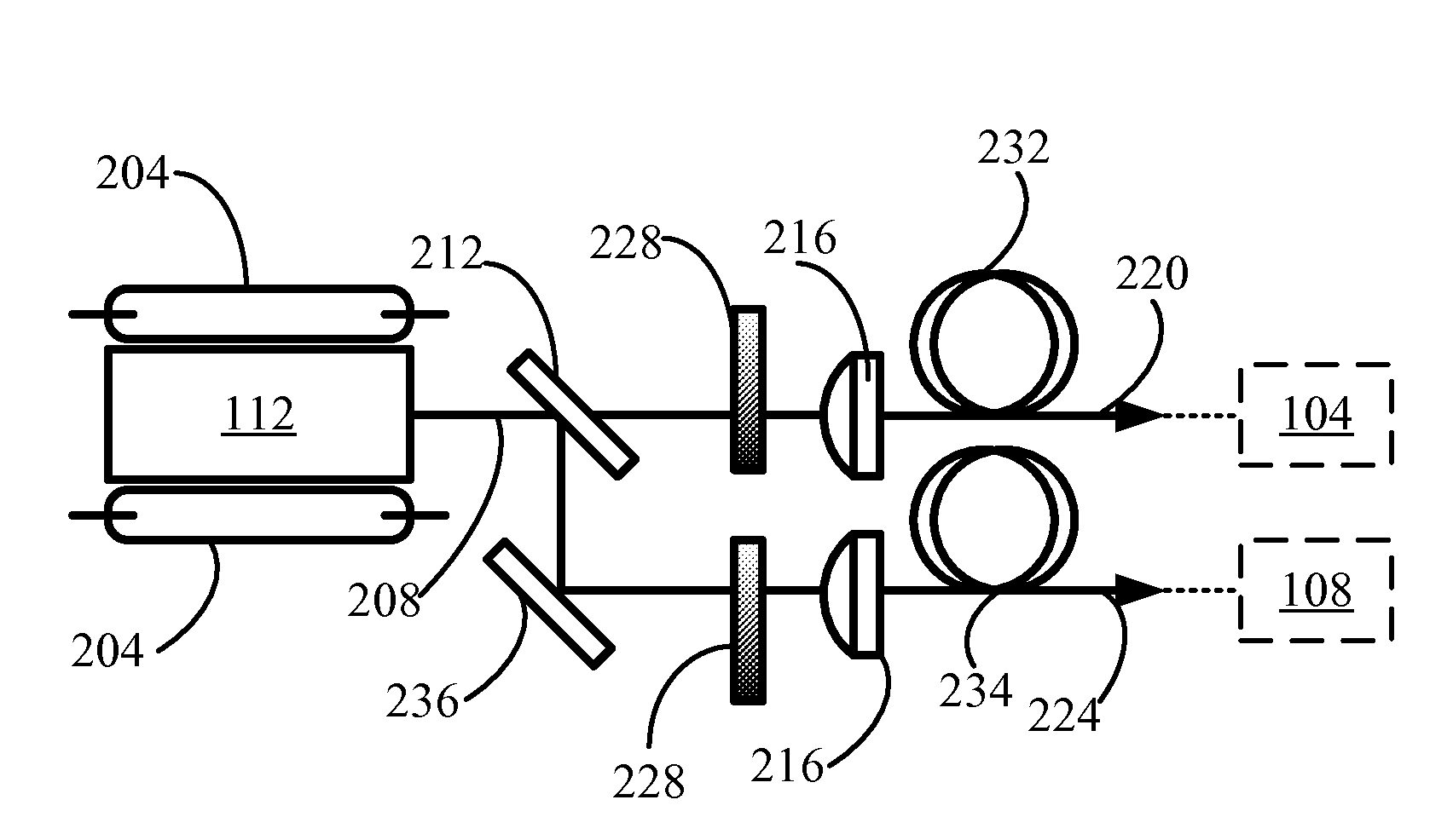
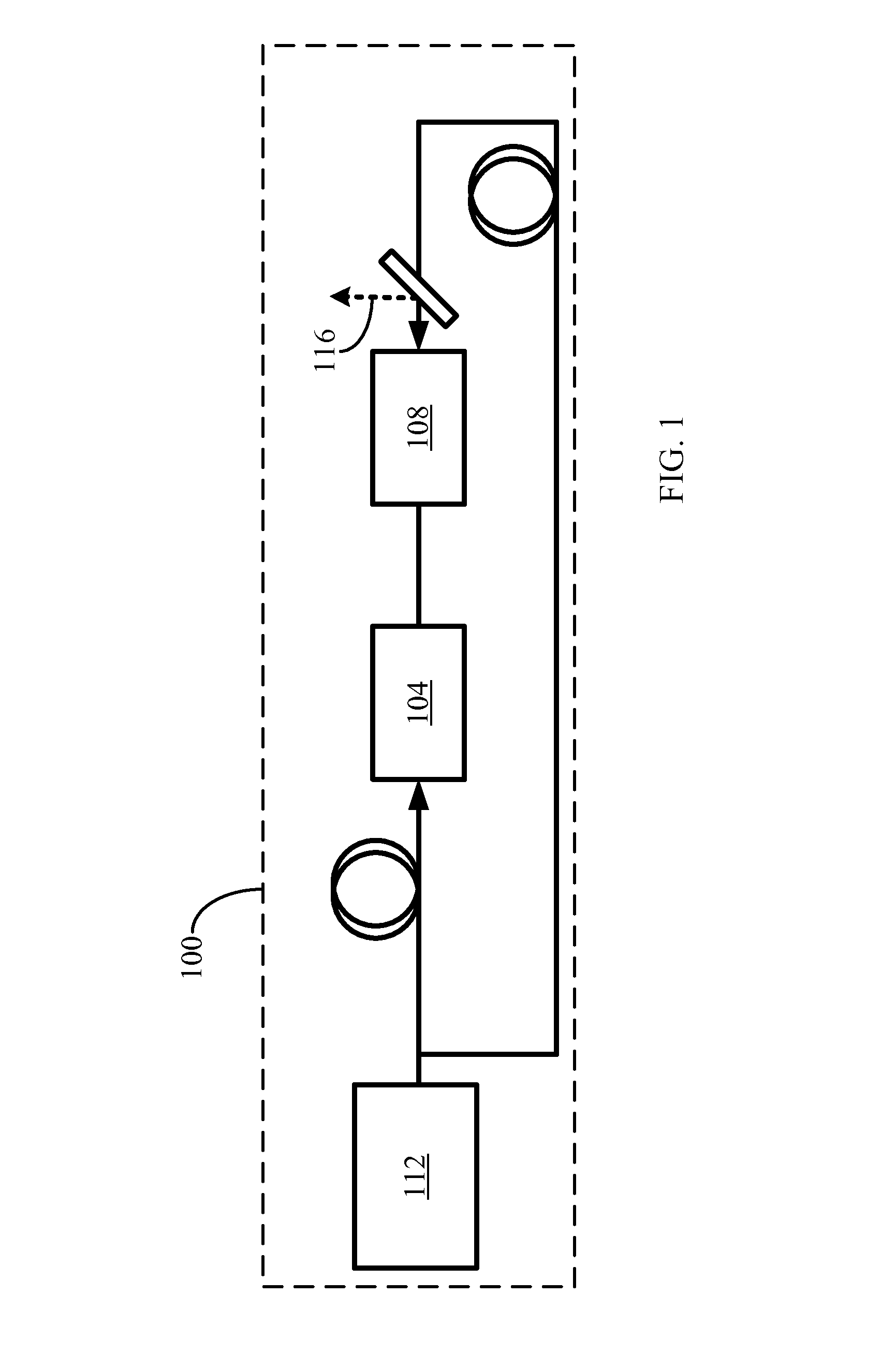
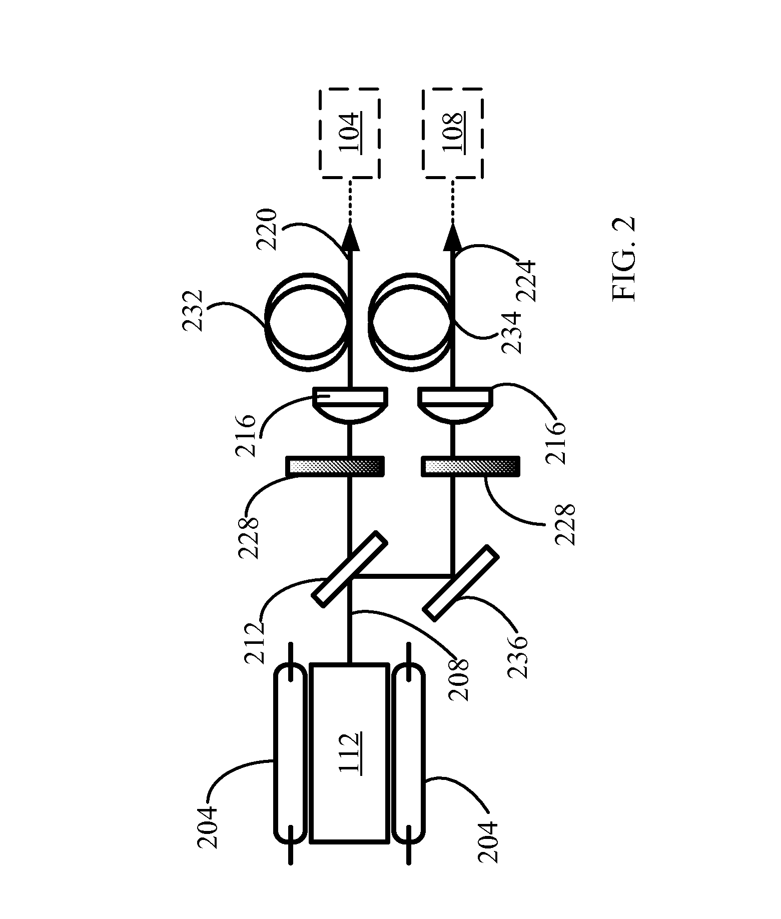
[0030]FIGS. 1-8 illustrate various exemplary embodiments of a high-energy, sub-nanosecond laser. The term “high-energy, sub-nanosecond laser,” as used herein, may refer to a laser that can provide an energy of 0.1 to 10 J with pulse duration of 10 to 900 psec. In general, a high-energy, sub-nanosecond laser can provide, for example, more effective micro machining, scientific spectroscopy, and medical treatments than a nanosecond laser commonly used. Accordingly, availability of a high-energy, sub-nanosecond laser may facilitate improvement of the existing applications and support development of new laser applications.

[0031]Microchip lasers are frequently used to “seed” the amplifying devices. ASE typically limits th...


PUM


Abstract

A MOPA laser system that includes a seed laser configured to output pulsed laser light, an amplifier configured to receive and amplify the pulsed laser light emitted by the seed laser; and a pump laser configured to deliver a pump laser beam to both the seed laser and the amplifier.

Description

TECHNOLOGY FIELD[0001]The present disclosure relates to laser systems and related methods. In particular, the present disclosure relates to laser systems and related methods for use in, for example, generating high-energy, sub-nanosecond pulses.DESCRIPTION OF RELATED ART[0002]Lasers are used in numerous applications in industry, research and medicine. Of special interest are lasers generating high energy and short duration pulses, for example, nanosecond and sub-nanosecond pulses. Such lasers would facilitate micro-processing applications of some precision materials. Such lasers could also address a number of scientific and technological applications, as well as certain medical procedures, where the short interaction time with the work piece or tissue can reduce heating effects and improve the interaction quality.[0003]Q-switched solid state lasers are currently used to generate short duration laser pulses. These pulses typical could have durations as short as a few nanoseconds, alt...

Claims


Application Information

Patent Timeline
Patent Type & Authority Applications(United States)
IPC IPC(8): H01S3/16H01S3/094H01S3/109H01S3/11H01S3/08H01S3/06H01S3/092H01S3/067
CPCH01S3/1633H01S3/092H01S3/094069H01S3/06754H01S3/1115H01S2301/02H01S3/061H01S3/1611H01S3/1643H01S3/109H01S3/08081H01S3/0625H01S3/0627H01S3/094053H01S3/094061H01S3/10023H01S3/113H01S3/1312H01S3/2308H01S3/0092H01S3/0617
Inventor BHAWALKAR, JAYANT D.SHANG, XIAOMINGQIU, JINZEJONES, CHRISTOPHER J.HSIA, JAMES
Owner CANDELA CORP
Why Eureka
Try Eureka