
Photobase generator

a generator and photobase technology, applied in the field of photobase generators, can solve the problems of large amount of photobase generators, low base generation rate, and inconvenient use of photobase generators, and achieve the effects of low cost, high catalytic activity, and efficient amine generation

Active Publication Date: 2016-10-13
SAN APRO
View PDF1 Cites 3 Cited by
  • Summary
  • Abstract
  • Description
  • Claims
  • Application Information

AI Technical Summary

Benefits of technology

The present invention introduces a photobase generator that has several technical advantages. Firstly, it is sensitive to light and can efficiently generate high-quality amines, such as tertiary amines and guanidines, which are known to have strong catalytic activity. Secondly, the photobase generator does not contain any harmful halogen ions that can cause metal corrosion. Thirdly, the photobase generator does not show any basicity before exposure to light, which means it is stable and does not affect the storage stability of the reactive composition. Lastly, the photobase generator is stable against heat and does not generate a base even when heated without being exposed to light. This makes it ideal for use in the production of cured materials. Overall, this patent introduces a photobase generator that can efficiently generate high-quality amines and produce cured materials without causing any harmful side effects.

Problems solved by technology

However, with regard to the photobase generators described in Patent Document 1 and Non-Patent Document 1, the basicity of the base generated is low (pKa<8), and the photobase generator is not suitable as the catalyst for a polymerization reaction or for a crosslinking reaction because the activity is low.
Moreover, since these amines have an active hydrogen atom, there has been a problem that a large amount of the photobase generator is required for allowing the reaction to proceed sufficiently because these amines themselves react with one another when used in a polymerization reaction or a crosslinking reaction of epoxides and isocyanates.
Moreover, the base generators described in Patent Documents 2 to 5 and Non-Patent Document 2 and the like have a problem that the performance is low when used as photo-latent base catalysts in a polymerization reaction or a crosslinking reaction of epoxides and isocyanates since the activity to light is low, and moreover, the base generator exerts a low effect when used in combination with a photosensitizer.

Method used


Image

  • Photobase generator
  • Photobase generator
  • Photobase generator

Examples


production example 1

Synthesis of thioxanthone-3-carboxylic acid (Intermediate a)

(1) Synthesis of 2-(phenylthio)-dimethyl terephthalate (Intermediate a-1)

[0101]In a reaction vessel, the inside of which was replaced with nitrogen, 43 g of dimethyl 2-nitroterephthalate (available from Tokyo Chemical Industry Co., Ltd.) and 100 mL of DMF were placed, and cooled to −10° C. with an ice-salt bath. To this, separately, a sodium thiophenolate solution prepared with 22 g of thiophenol, 8 g of sodium hydride and 60 mL of DMF was added dropwise over a period of 1 hour. The contents were stirred for 3 hours at room temperature, and then, charged into water. After being extracted with ethyl acetate and removed from the aqueous layer, water washing was performed three times and the organic layer was concentrated. The concentrated organic layer was treated with hexane to obtain 45 g of a white solid. It was confirmed by 1H-NMR that this white solid was (Intermediate a-1).

(2) Synthesis of 2-(phenylthio)-terephthalic ac...

production example 2

Synthesis of 2-mercaptothioxanthone (Intermediate b)

[0104]In a reaction vessel, 300 mL of concentrated sulfuric acid was placed, and to this, 16 g of dithiosalicylic acid (available from Wako Pure Chemical Industries, Ltd.) was added in small portions. The contents were stirred for 30 minutes, and cooled to 5° C. with an ice bath. To this, 120 g of thiophenol was added dropwise. After being stirred for 1 hour at room temperature, the contents were allowed to undergo a reaction for 5 hours at 80° C., and then, again cooled to room temperature. To 5 L of water at 80° C., the reaction liquid was added in small portions under stirring. After being cooled to room temperature, a solid precipitated was filtered. The solid was recrystallized from dioxane / water to obtain 22 g of a yellow solid. It was confirmed by 1H-NMR that this solid was (Intermediate b).

production example 3

Synthesis of 2-bromomethylthioxanthone (Intermediate c)

(1) 2-Methylthioxanthone (Intermediate c-1)

[0105]In a reaction vessel, 70 mL of concentrated sulfuric acid was placed, and to this, 10 g of dithiosalicylic acid (available from Wako Pure Chemical Industries, Ltd.) was added and stirred at room temperature for 1 hour. The contents were cooled with an ice bath and 25 g of toluene was added dropwise while keeping the temperature thereof at 20° C. or lower. After dropping, the temperature thereof was returned to room temperature, and furthermore, stirring was performed for 2 hours. This reaction liquid was poured into 800 g of ice water. A yellow solid precipitated was filtered off and dissolved in 200 g of dichloromethane, after which water washing was performed. The organic layer was concentrated to obtain 9 g of a yellow solid. It was confirmed by: 1H-NMR that this yellow solid was Intermediate (c-1).

(2) Synthesis of 2-bromomethylthioxanthone (Intermediate c)

[0106]In a reaction v...


PUM

PropertyMeasurementUnit
pKaaaaaaaaaaa
pKaaaaaaaaaaa
pKaaaaaaaaaaa

Abstract

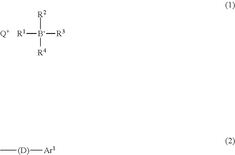
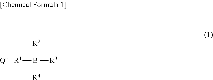
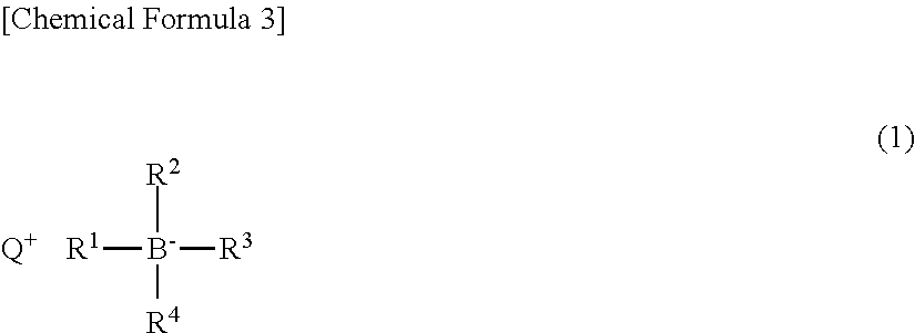
Provided are a photobase generator having higher sensitivity to light than do conventional photobase generators, and a photosensitive resin composition containing the photobase generator. The present invention is a photobase generator characterized in containing a salt represented by general formula (1). (In formula (1), R1-R4 are mutually independent groups represented by general formula (2), C1-18 alkyl groups, or Ar, with at least one being a group represented by general formula (2); in formula (2), (D) is a divalent group bonded on at least one side to elemental boron, and Ar1 is the same as the aforementioned Ar; and Q+ is a monovalent onium cation.)

Description

TECHNICAL FIELD[0001]The present invention relates to a photobase generator generating a base by photoirradiation. More particularly, the present invention relates to a photobase generator suitably used for the production of a material to be cured by utilizing a base generated by photoirradiation (for example, a coating agent or a coating material) or a product or a member formed after being subjected to patterning in which the difference in solubility to a developing solution between the exposed part and the unexposed part is utilized (for example, an electronic component, an optical product, a forming material for an optical component, a layer forming material or an adhesive agent).BACKGROUND ART[0002]As a photobase generator generating a base by being subjected to exposure, there have been known various photobase generators such as photobase generators generating primary amines or secondary amines and photobase generators generating a strong base (tertiary amines, pKa 8 to 11) an...

Claims


Application Information

Patent Timeline
Patent Type & Authority Applications(United States)
IPC IPC(8): G03F7/004C07D487/04C07D233/58G03F7/038C07C279/04C07F9/572C07F9/06C07F5/02C07D233/60
CPCG03F7/0045C07F5/02C07D487/04C07D233/58G03F7/038C07C279/04C07F9/5721C07F9/065C07D233/60C07D233/54C07D335/16C07D409/06C07F9/572G03F7/004G03F7/0382G03F7/0392C07F5/027
Inventor IKEDA, TAKUYASHIRAISHI, ATSUSHI
Owner SAN APRO
Learn More