Discharge ionization detector

a technology of ionization detector and discharge current, which is applied in the field of ionization detector, can solve the problems of low detection limit, low ionization efficiency of alcohol, aromatic substances, chlorine-based substances, etc., and achieve the effect of reducing baseline current, suppressing leakage current, and reducing baseline curren

Active Publication Date: 2016-11-24
SHIMADZU CORP
View PDF5 Cites 6 Cited by
  • Summary
  • Abstract
  • Description
  • Claims
  • Application Information

AI Technical Summary

Benefits of technology

[0032]With the discharge ionization detector according to the present invention, it is possible to suppress leakage current between a pair of electrodes for ion collection and to reduce baseline current caused by the leakage current. As a result, it is possible to reduce baseline current even, for example, in a BID with Ar used as a plasma generation gas, in which baseline current is difficult to be reduced only by the reduction of impurities included in a plasma generation gas or the other gases and impurities emitted from members exposed in a gas passage. It is thereby possible to enhance the SN ratio of a detection signal as well as to improve the lower limit of detection.

Problems solved by technology

However, the FID has drawbacks: firstly, its ionization efficiency is low, and therefore, the lowest detection limit is not low enough; secondly, the ionization efficiencies for alcohols, aromatic substances, and chlorine-based substances are low; and thirdly, it requires hydrogen, which is a hazardous substance, and therefore, an explosion-proof apparatus or similar kind of special equipment must be provided, which makes the entire system difficult to operate.
Therefore, as with FIDs, it is not possible to ionize inorganic compounds.
However, this means that it is insensitive to water.

Method used


Image

  • Discharge ionization detector
  • Discharge ionization detector
  • Discharge ionization detector

Examples


first embodiment

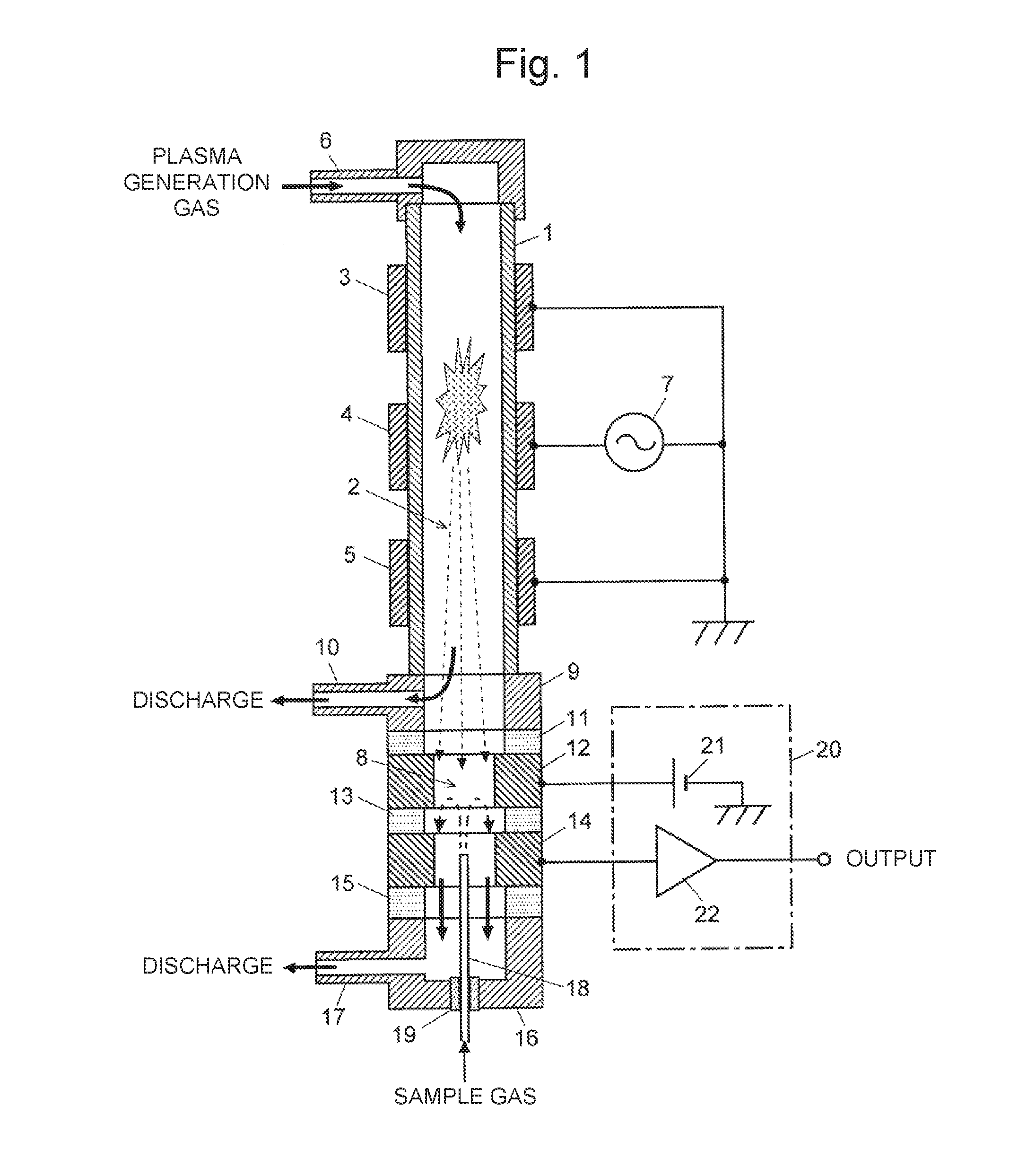
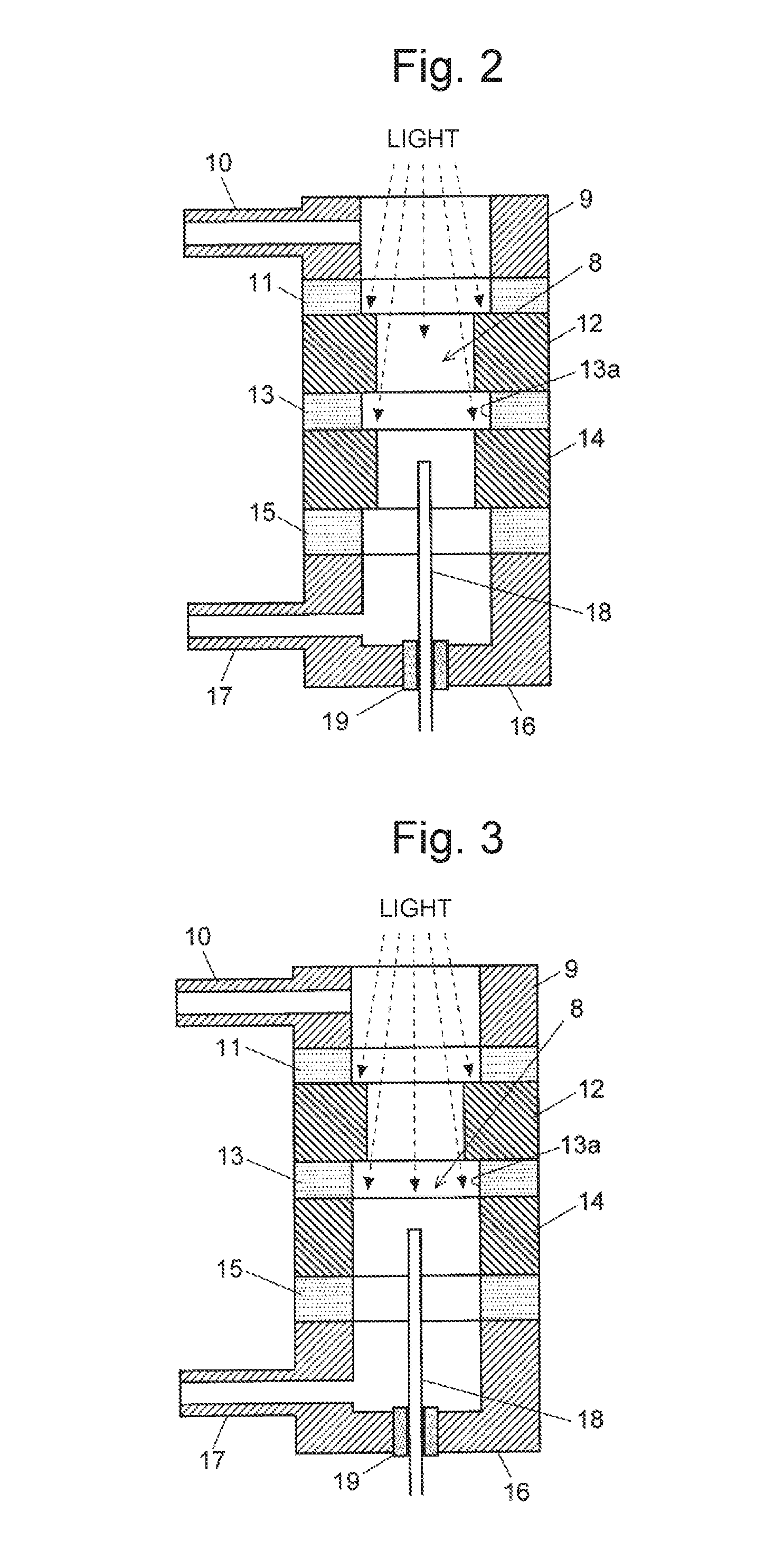
[0042]FIG. 1 is a schematic configuration diagram of a BID in a first embodiment. FIG. 2 is an enlarged view of an ion collector of the BID in this embodiment.

[0043]The BID of the present embodiment has a dielectric cylindrical tube 1 whose inner space serves as a first gas passage 2. On the outer wall surface of the dielectric cylindrical tube 1, annular plasma generation electrodes 3-5 made of an electrically conductive material (e.g. stainless steel or copper) are circumferentially provided at predetermined intervals in the flowing direction of the gas. A gas supply tube 6 is connected to the upper end of the dielectric cylindrical tube 1. Plasma generation gas that also serves as dilution gas is supplied through this gas supply tube 6 into the first gas passage 2. The wall of the dielectric cylindrical tube 1 between the first gas passage 2 and each of the plasma generation electrodes 3-5 functions as a dielectric coating layer which covers the surface of the plasma generation e...

second embodiment

[0053]FIG. 3 is an enlarged view of an ion collector of a BID in a second embodiment of the present invention. Components identical to those of the BID shown in FIG. 1 and FIG. 2 are denoted by the same reference signs.

[0054]In this BID in the second embodiment, the positional relationship between the bias electrode 12 and the insulating member 13 is the same as that in the first embodiment. As in the first embodiment, light from plasma is hardly cast on the surface 13a of the insulating member 13 because of light shielding by the bias electrode 12.

[0055]In the BID in the aforementioned first embodiment, the bias electrode 12 and the collector electrode 14 have the same inner diameter, and the same members can be used. However, the inner diameter of the collector electrode 14 is not necessarily the same as that of the bias electrode 12. An increase in baseline current is caused also by the photoelectric effect by light directly cast on the collector electrode 14. For this reason, av...

third embodiment

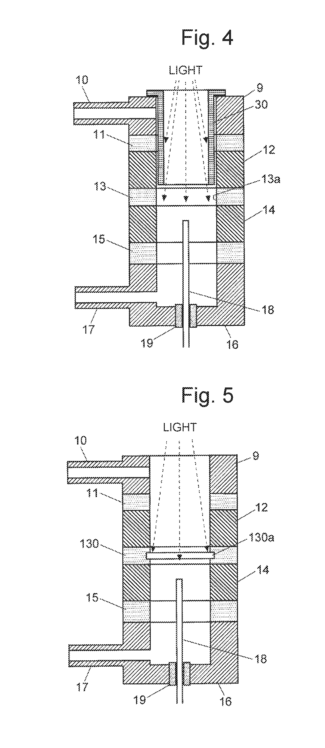
[0057]FIG. 4 is an enlarged view of an ion collector of a BID in a third embodiment of the present invention. In this BID in the third embodiment, the bias electrode 12, the insulating member 13 and the inner diameter of the collector electrode 14 are identical, and an additional light shielding member 30 is provided by being inserted into the second gas passage 8. The light shielding member 30 has such a shape that a flange is formed at one opened end of a cylindrical body. The light shielding member 30 is made of, for example, an insulator such as a machinable ceramic. In this BID in the third embodiment, light emitted from plasma is shielded by the cylindrical body of the light shielding member 30 and not cast directly on the surface 13a of the insulating member 13. Therefore, as in the aforementioned embodiments, leakage current between the bias electrode 12 and the collector electrode 14 is suppressed, whereby baseline current in a detection signal can be reduced.


PUM

PropertyMeasurementUnit
light energyaaaaaaaaaa
frequencyaaaaaaaaaa
AC voltageaaaaaaaaaa

Abstract

To suppress baseline current other than baseline current derived from the ionization of impurities, and to achieve the enhancement of the SN ratio of a detection signal and the improvement of the lower limit of detection, the inner diameter of a bias electrode for collecting an ion derived from a sample component is made smaller than the inner diameter of an insulating member separating the bias electrode and a collector electrode. Light emitted from plasma formed by dielectric barrier discharge is shielded by the bias electrode, so that the light is not cast directly on the surface of the insulating member. Therefore, the photoelectric effect caused by casting light of high energy does not occur on the surface of the insulating member, whereby a decrease in electric resistance of the surface can be prevented.

Description

TECHNICAL FIELD[0001]The present invention relates to a discharge ionization detector for ionizing a sample by mainly using light emitted from plasma generated by discharge such as dielectric barrier discharge, and detecting the resultant ion current.BACKGROUND ART[0002]As a detector for a gas chromatograph (GC), various types of detectors have been put to practical use, such as a thermal conductivity detector (TCD), electron capture detector (ECD), flame ionization detector (FID), flame photometric detector (FPD), and flame thermionic detector (FTD). Among these detectors, the FID is most widely used, particularly for the purpose of detecting organic substances. The FID is a device that ionizes sample components in a sample gas by hydrogen flame and detects the resultant ion current. It has a wide dynamic range (the sample-concentration range within which the detection sensitivity shows an adequate linearity) of six to seven digits. However, the FID has drawbacks: firstly, its ioni...

Claims


Application Information

Patent Timeline
Patent Type & Authority Applications(United States)
IPC IPC(8): G01N27/66
CPCG01N27/66G01N30/64G01N2030/642
Inventor SHINADA, KEI
Owner SHIMADZU CORP
Why Eureka
Try Eureka