
System and method for fluidized bed reduction of powdered iron ore

a technology of fluidized bed and powdered iron ore, which is applied in the field of chemical engineering and metallurgy, can solve the problems of affecting the efficiency the temperature of the fluidized bed cannot be maintained at 800° c. or above, and the system has been shut down, etc., and achieves the reduction rate of powdered iron ore, the effect of increasing coal gas utilization and high operating gas velocity

Active Publication Date: 2016-12-01
BEIJING ZHONGKAIHONGDE TECH +1
View PDF0 Cites 4 Cited by
  • Summary
  • Abstract
  • Description
  • Claims
  • Application Information

AI Technical Summary

Benefits of technology

The present invention is a system and method for reducing powdery iron ore on a fluidized bed. It has advantages such as high reducing efficiency, economy, and suitability for large scale production. The system includes a gas inlet, gas outlet, and a pipeline burner for providing heat for pre-reduction in the reactor. The iron ore powder is reduced at a pressure of less than 1 atm, which overcomes the deficiency of high-power gas compression resulting from high pressure in traditional technology. The reduction of coal gas is operated in series-parallel mode, which increases the coal gas utilization and enhances the reduction rate of the powdery iron ore. The present invention has high reducing efficiency, low energy consumption, and improves economy in the process of reducing powdery iron ore.

Problems solved by technology

The current pig-iron smelting mainly employs the blast furnace technology, which requires uses of coke and pellet, involving a relatively long workflow.
However, the system has been shut down for market reasons since November 2001.
However, from reports in existing documents, the Circofer technology only passed the above pilot scale test, without further reported pilot scale test or industrialized application.
However, if the gas is not preheated, the temperature of the fluidized bed cannot be maintained at 800° C. or above, which is required for the reaction.
However, the reducing capability of the hot gas would be weakened if the gases generated during the melting and separating process, such as CO2, H2O, etc., are not removed.
As the reaction process absorbs heat in general, when no preheater is set up thereamong, the temperature of the fluidized bed falls gradually, reaching as low as 400-500° C. in the last stage fluidized bed (the first fluidized bed), resulting in poor reducing capabilities.
Though the temperature of the gas is elevated by direct partial combustion, the CO2 and H2O generated from combustion would greatly lower the reduction potential and weaken the reducing capability of the gas, which is quite adverse to the reduction process.
However, it is not operationally practical due to the wide range, because ten times of difference between the highest and the lowest operating pressures means the same ten times of difference between the highest and the lowest linear speeds of the fluidized beds, and generally it is hard for fluidized beds to have such operational flexibility.
Therefore, a large amount of gas is required in the reduction process.
(2) low reduction efficiency: Although most processes use four-stage fluidized beds for reduction, no intermediary heat supplementation for the gas passing from the fourth stage to the first stage fluidized beds in series results in gradual reduction of the reaction temperature from the fourth stage to the first stage, with the temperature in the first-stage fluidized bed of only 400-500° C. Since iron ore exhibits slow reduction kinetics under a temperature below 700° C., the last two stages of the conventional four-stage fluidized beds play a minor role in reduction, resulting in a low overall reduction efficiency.

Method used


Image

  • System and method for fluidized bed reduction of powdered iron ore
  • System and method for fluidized bed reduction of powdered iron ore

Examples


example 1

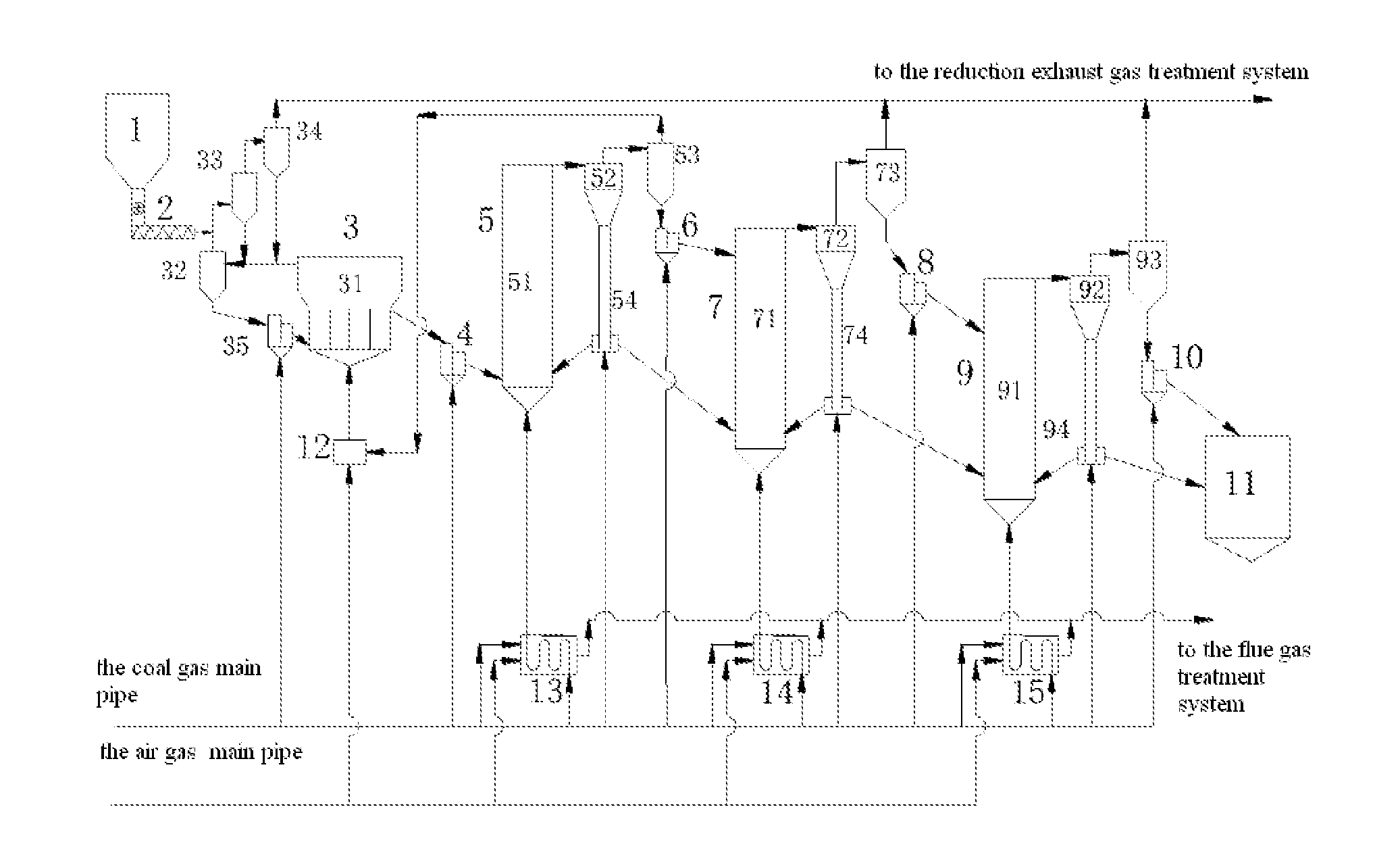
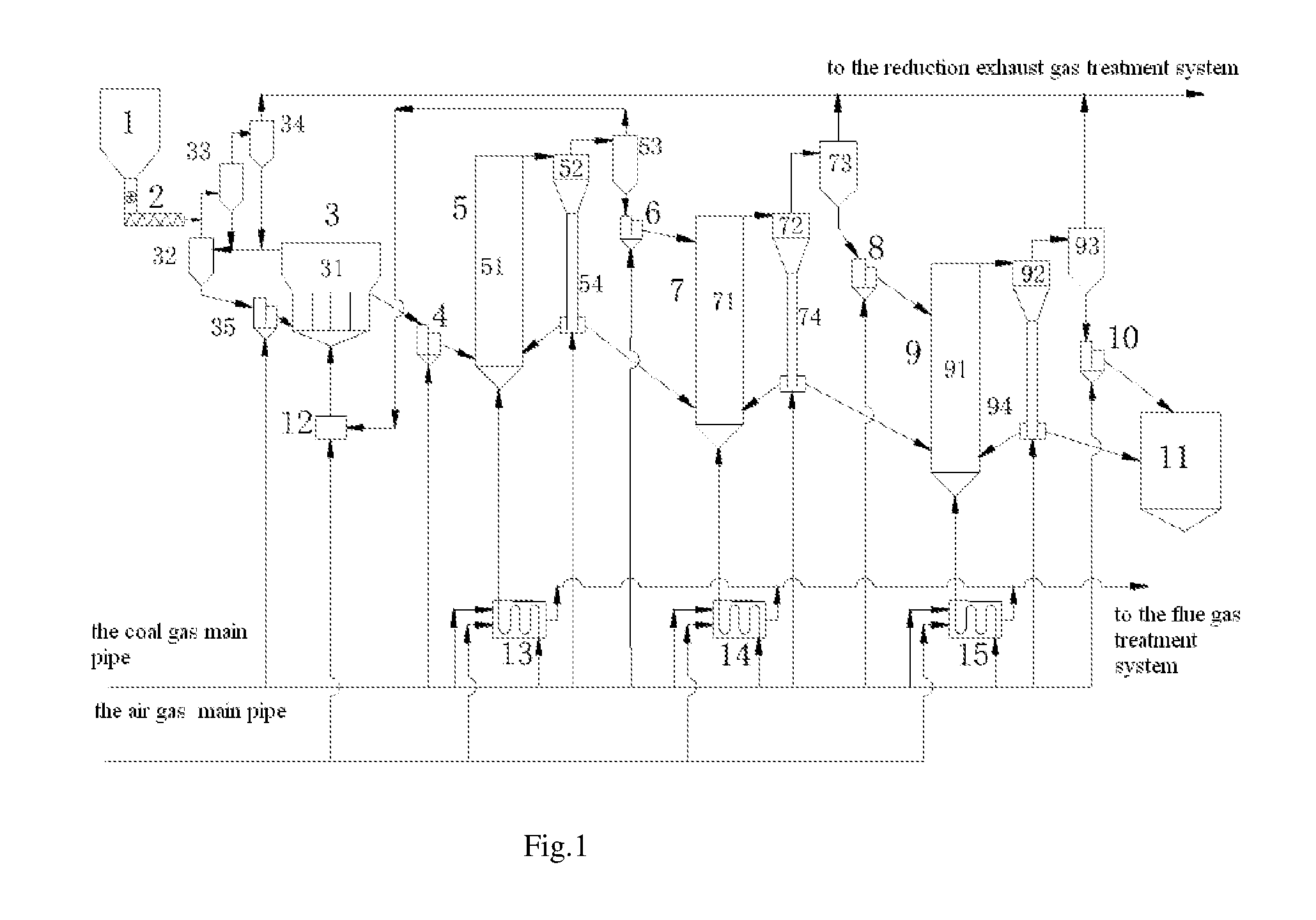
[0044]A system for reducing powdery iron ore on a fluidized bed comprises: a bin 1, a screw feeder 2, a bubbling fluidized bed 3, a primary feeder 4, a primary circulating fluidized bed 5, a secondary feeder 6, a secondary circulating fluidized bed 7, a tertiary feeder 8, a tertiary circulating fluidized bed 9, a discharger 10, a product bin 11, a pipeline burner 12, a primary coal gas preheater 13, a secondary coal gas preheater 14, and a tertiary coal gas preheater 15.

[0045]The bubbling fluidized bed 3 comprises a fluidized bed body 31, a first cyclone separator 32, a second cyclone separator 33, a third cyclone separator 34 and a feeder 35.

[0046]The primary circulating fluidized bed 5 comprises a primary riser 51, a fourth cyclone separator 52, a fifth cyclone separator 53 and a primary circulating dipleg 54.

[0047]The secondary circulating fluidized bed 7 comprises a secondary riser 71, a sixth cyclone separator 72, a seventh cyclone separator 73 and a secondary circulating diple...

example 2

[0060]The method of reducing powdery iron ore by the system for reducing powdery iron ore on a fluidized bed according to Example 1 comprises the following steps: the powdery iron ore is sent to the inlet of the second cyclone separator 33 from the bin 1 via the screw feeder 2, the powdery iron ore separated and collected by the second cyclone separator 33 and the third cyclone separator 34 respectively enters into the inlet of the first cyclone separator 32 through the pipeline, and then enters into the first cyclone separator 32 for gas-solid separation after being mixed with the exhaust gas discharged by the fluidized bed body 31, and the powdery iron ore is discharged from the feed outlet at the bottom of the first cyclone separator 32 and then enters into the fluidized bed body 31 via the feeder 35. The powdery iron ore is subjected to a pre-reduction reaction in the bubbling fluidized bed 3, and then discharged from the feed outlet at the upper portion of the fluidized bed bod...

example 3

[0062]The iron ore comprised of 85.2% Fe2O3, 2.7% CaO, 1.8% MgO, 3.2% Al2O3 and 7.1% SiO2 (percentage by mass) was processed according to the present invention The powdery iron ore had a particle size of 0.10-1.0 mm. The powdery iron ore was pre-reduced in the bubbling fluidized bed through the above process of the present invention, and Fe2O3 in the powdery iron ore could be reduced to FeO at 650° C. for 70 min, at 700° C. for 35 min, or at 750° C. for 20 min. The pre-reduced powdery iron ore was reduced in a three-stage circulating fluidized bed through the above process of the present invention. When each stage of the circulating fluidized bed was operated under the conditions of reduction temperature of 800° C., reduction time of 70 minutes and operating gas velocity of 5 m / s with a corresponding maximum operating pressure of 0.35 atm, the metallization ratio of the powdery iron ore from the outlet of the tertiary circulating fluidized bed reached 83.5%. When each stage of the c...


PUM

PropertyMeasurementUnit
temperatureaaaaaaaaaa
gas velocityaaaaaaaaaa
operating pressureaaaaaaaaaa

Abstract

A system for fluidized bed reduction of powdered iron ore. Use of high-gas-velocity processing accelerates iron ore reduction speed and greatly improves the gas-treatment capabilities of a unit-cross-sectional fluidized bed. Use of parallel connections involving reduced coal gas lessens the volume of gas passing through a single-stage fluidized bed. Use of serial / parallel-connection processing involving reduced coal gas increases the coal gas utilization rate. The invention achieves the highly-effective reduction of powdered iron ore in a fluidized bed under near-atmospheric pressure. A reduction method based on the present system is also disclosed.

Description

FIELD OF THE INVENTION[0001]The present invention belongs to the fields of chemical engineering and metallurgy, and particularly relates to a system and method for reducing powdery iron ore using a fluidized bed.BACKGROUND OF THE INVENTION[0002]The current pig-iron smelting mainly employs the blast furnace technology, which requires uses of coke and pellet, involving a relatively long workflow. Non-blast furnace ironmaking technologies have been paid more and more attention for lessening the dependence on coke. Non-blast ironmaking technologies can be divided into two types: direct reduction and melting reduction. The product from direct reduction is sponge iron obtained from the reduction of iron ore concentrate and mainly used as raw material for electric furnace steelmaking. In melting reduction, the sponge iron is further melted so as to obtain liquid iron after separation of slag-iron. Both direct reduction and melting reduction need to undergo a gas-solid phase reduction proce...

Claims


Application Information

Patent Timeline
Patent Type & Authority Applications(United States)
IPC IPC(8): C21B13/00F27B15/00F27B15/10C21B13/14
CPCC21B13/0033F27B15/10F27B15/003C21B13/146F27B15/02F27B15/14F27B15/18Y02P10/134C21B11/00C21B13/00Y02P10/20
Inventor ZHU, QINGSHANFAN, CHUANLINLI, HONGZHONGXIE, ZHAOHUI ZMU, WENHENGWANG, CUNHUJIAO, XINGANG
Owner BEIJING ZHONGKAIHONGDE TECH
Learn More