Plasma elements in medical imaging devices

Inactive Publication Date: 2016-12-22
ANDERSON THEODORE R
View PDF2 Cites 2 Cited by
  • Summary
  • Abstract
  • Description
  • Claims
  • Application Information

AI Technical Summary

Benefits of technology

The present invention provides plasma elements for use in medical imaging machines such as gradient coils, RF transmitting elements, and RF receiving elements. The use of plasma elements improves machine performance, reduces acoustic noise, and improves image quality. The plasma based RF elements have reduced coupling effects and interference when judiciously switched, thereby improving quality and allowing multiple portions of the patient to be scanned at the same time, which reduces the scan time. The plasma conductor includes a container or vessel that contains a material that forms a plasma when ignited or vaporized and ionized. The plasma conductor is electrically connected to the gradient control system and produces a time-dependent gradient magnetic field in each gradient coil. The plasma based gradient coils are less susceptible to vibration induced by the magnetic fields, thereby reducing or eliminating the acoustic noise from a scan, which removes one source of patient anxiety. The RF transmitting elements and / or the RF receiving elements include plasma elements, which reduces or eliminates the coupling effects and interference between the RF elements. The multiple, nested RF elements allows for multiple scans to be performed at the same time, thereby decreasing scan time with reduced interference.

Problems solved by technology

One issue with MRI machines is that the gradient coils are solid, metal conductors.
The Lorentz force produces minute expansions and contractions of the coil itself, which because of their solid construction, results in vibration that produces acoustic noise.
The noise often sounds like loud banging or clicking to the patient.
Another issue with MRI machines is that the RF transmitting and receiving elements, or antennas, are metal conductors.
Each one of the pair of transmitting and receiving elements introduce RF interference (RFI) and / or electromagnetic interference (EMI), which creates noise and reduces signal sensitivity.
Additionally, the elements are subject to thermal noise generated by the metal conductor forming the element.
The thermal noise is often a significant factor considering the low level of emitted RF energy by the excited nuclei.
Yet another issue with MRI machines is that different frequencies of RF energy are often used, depending upon the nuclei to be excited and the operating conditions of the machine.
One issue with such a combined MRI / PET machine is that the metal elements and coils interfere with the gamma radiation.
Such interference reduces the sensitivity and accuracy of the combined MRI / PET machine.

Method used


Image

  • Plasma elements in medical imaging devices
  • Plasma elements in medical imaging devices
  • Plasma elements in medical imaging devices

Examples


first embodiment

[0075]FIG. 8 illustrates a schematic of an RF exciter 218-A for a plasma device 710, such as a transmitting element 106. The material inside the vessel 714, before it changes state to be plasma 716, must be excited or ionized. FIG. 8 illustrates one such excitation circuit 218-A that creates a plasma 716 inside the vessel 714. In various embodiments, the RF exciter 218 includes an excitation circuit 218-A such as the one illustrated in FIG. 8.

[0076]The excitation circuit 218-A is a Marx Generator that generates high-voltage pulses from a low voltage direct current power supply 802. The plasma device 710 includes one or more electrical connections 812 that are electrodes that complete the electrical circuit between the external components 218 and the plasma 716 inside the vessel 714. A plasma 716 is generated when a material become an ionized gas through excitation or ignition. Generating a plasma 716 is accomplished by the application of an electric and / or magnetic field, RF heating...

second embodiment

[0079]FIG. 9 illustrates a schematic of an exciter 218-B for a plasma device 710. The excitation circuit 218-B is a modified Marx Generator that has insulated gate bipolar transistors (IGBT) as switches 902-A, 902-B instead of the spark gaps 808-A, 808-B. The switches 902-A, 902-B perform similar functions as the spark gaps 808-A, 808-B, except that operation of the switches 902-A, 902-B is controlled by signals applied to the gate connections 804-A, 804-B instead of when the charge accumulates on the capacitors 806 such that the breakdown voltage is reached.

[0080]A first signal at a triggering level is applied to the gate connection 904-A of the first switch 902-A, which places the capacitors 806-A, 806-B in series, effectively doubling the voltage of the power source 802. A second signal at a triggering level is applied to the gate connection 904-B of the second switch 902-B at about the same time as the first signal is applied to the first gate connection 904-A. The second switch...

third embodiment

[0081]FIG. 10 illustrates a schematic of an exciter 218-B for a plasma device 710. The illustrated embodiment of the exciter 218-C is a general form of an excitation circuit. A timer 1002 provides a trigger signal to the gate connection 904-C of a switch 902-C. The switch 902-C is in series with a high voltage power source 1004, which is connected to the lead 812 of the plasma device 710.

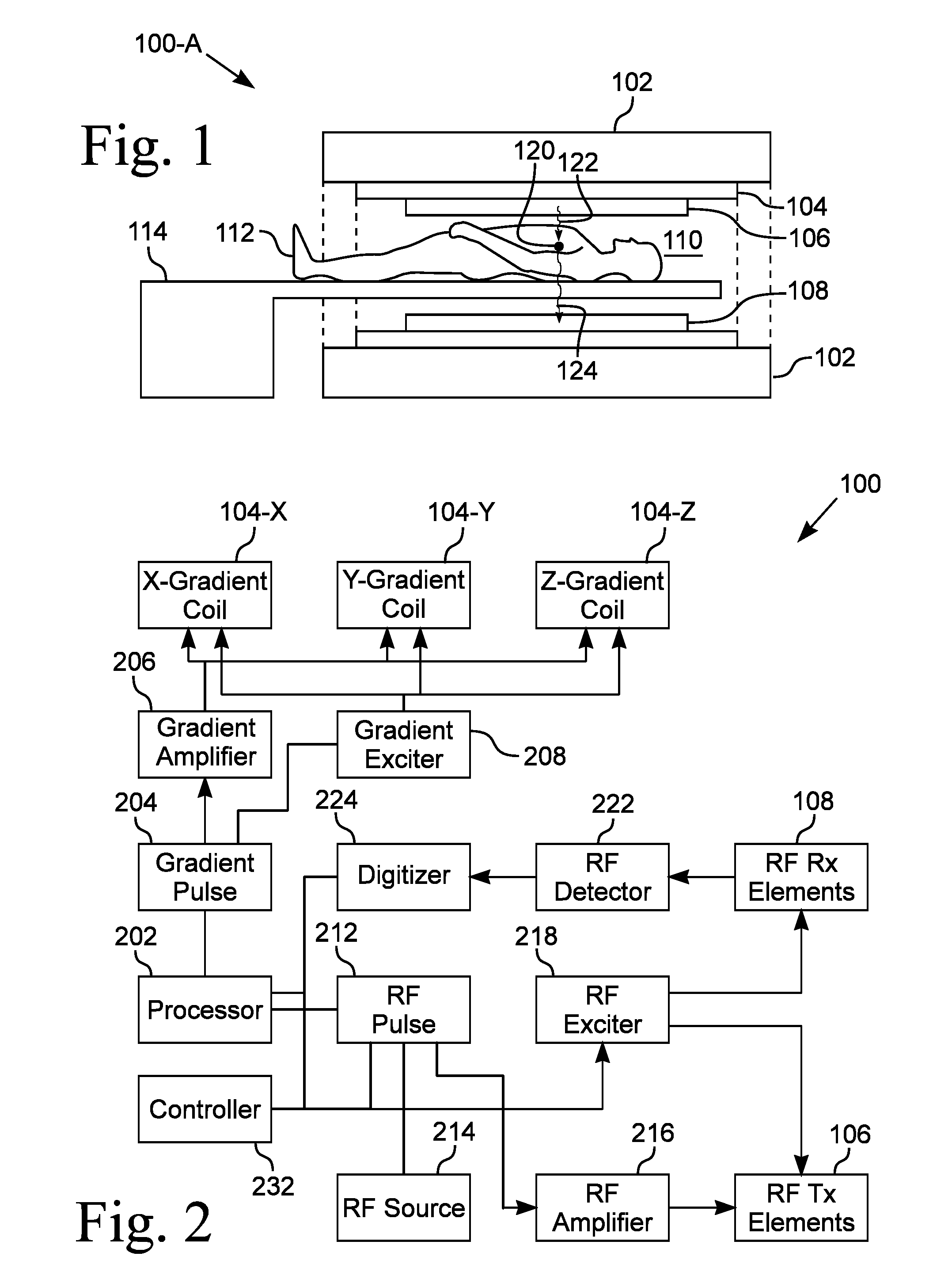
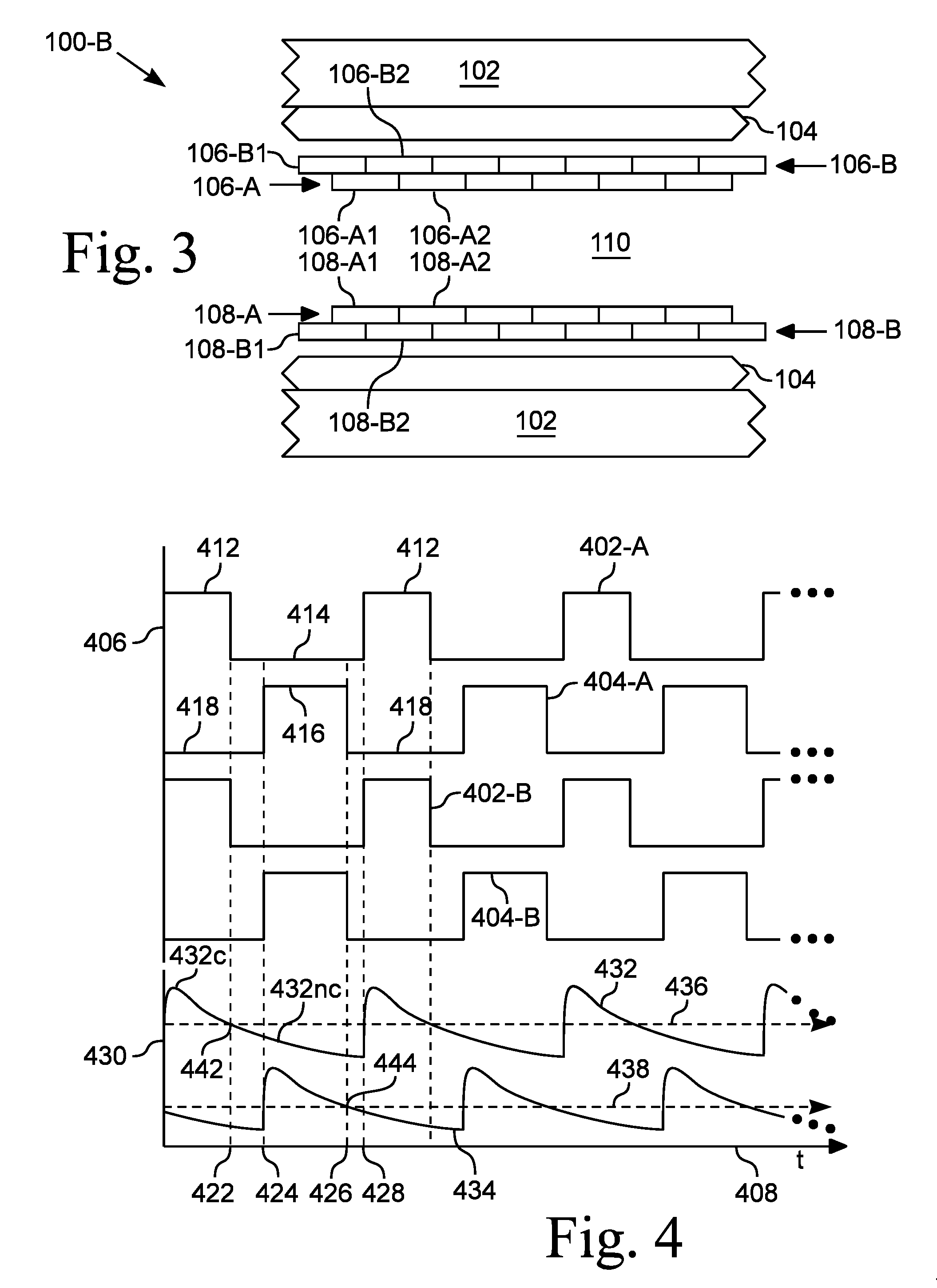
[0082]The timer 1002, in various embodiments, is a circuit of discrete components, an integrated circuit, or a timer software program controlling an output of the processor 202 or controller 232. The timer 1002 provides a timing signal, such as the ones that generate the waveforms 402, 404 illustrated in FIG. 4, to the switch 902-C. The timer 1002 and switch 902-C form a pulse driver circuit that drives a high voltage source 1004. In one embodiment, the source 1004 is an excitation circuit 218-B, such as the one illustrated in FIG. 8, with the switch 902-C driving the gate connections 904-A, 904-B.

[...


PUM


Abstract

Apparatus for a nuclear resonance imaging (MRI) machine that includes plasma elements. The MRI machine includes gradient coils that generate time-dependent gradient magnetic fields, transmitting elements that excite target molecules with RF energy, and receiving elements responsive to RF energy emitted by the excited molecules. The gradient coils include plasma conductors in which the plasma is ignited by an exciter. The plasma conductors are electrically connected to a gradient amplifier that outputs a signal to produce the gradient fields. The transmitting elements are plasma devices configured to emit RF energy. The receiving elements are plasma devices responsive to emitted RF energy. An RF exciter selectively and alternatingly ignites said plasma devices to avoid coupling and interference between them.

Description

BACKGROUND[0001]1. Field of Invention[0002]This invention pertains to plasma devices installed in medical imaging devices. More particularly, this invention pertains to plasma devices as gradient coils and as radio frequency transmitting and receiving elements in medical imaging devices, such as magnetic resonance imaging devices.[0003]2. Description of the Related Art[0004]Advances in medical science have resulted in several choices for non-invasive diagnostic imaging beyond x-ray images. Magnetic resonance imaging (MRI) is one such non-invasive imaging that is now available. Positron emission tomography (PET) is another such imaging technique. A recent advance is a combination of magnetic resonance imaging and positron emission tomography for a MRI / PET device.[0005]Magnetic resonance imaging is based on the science of nuclear magnetic resonance (NMR). An MRI device uses magnetic and radio waves to produce detailed morphological information of the organs, tissues and structures wit...

Claims


Application Information

Patent Timeline
IPC IPC(8): G01R33/385G01R33/36
CPCG01R33/36G01R33/3852G01R33/34007G01R33/3657G01R33/385G01R33/3854G01R33/481G01R33/3614
Inventor ANDERSON, THEODORE R.
Owner ANDERSON THEODORE R
Why Eureka
Try Eureka