Ceramic Phosphor Target
a phosphor target and ceramic technology, applied in the field of projection and display optics applications, can solve the problems of large absorption of incident light and considerable backscattering of luminescent light, and achieve the effects of improving performance, increasing incident laser intensities, and increasing power and radian
- Summary
- Abstract
- Description
- Claims
- Application Information
AI Technical Summary
Benefits of technology
Problems solved by technology
Method used
Image
Examples
first embodiment
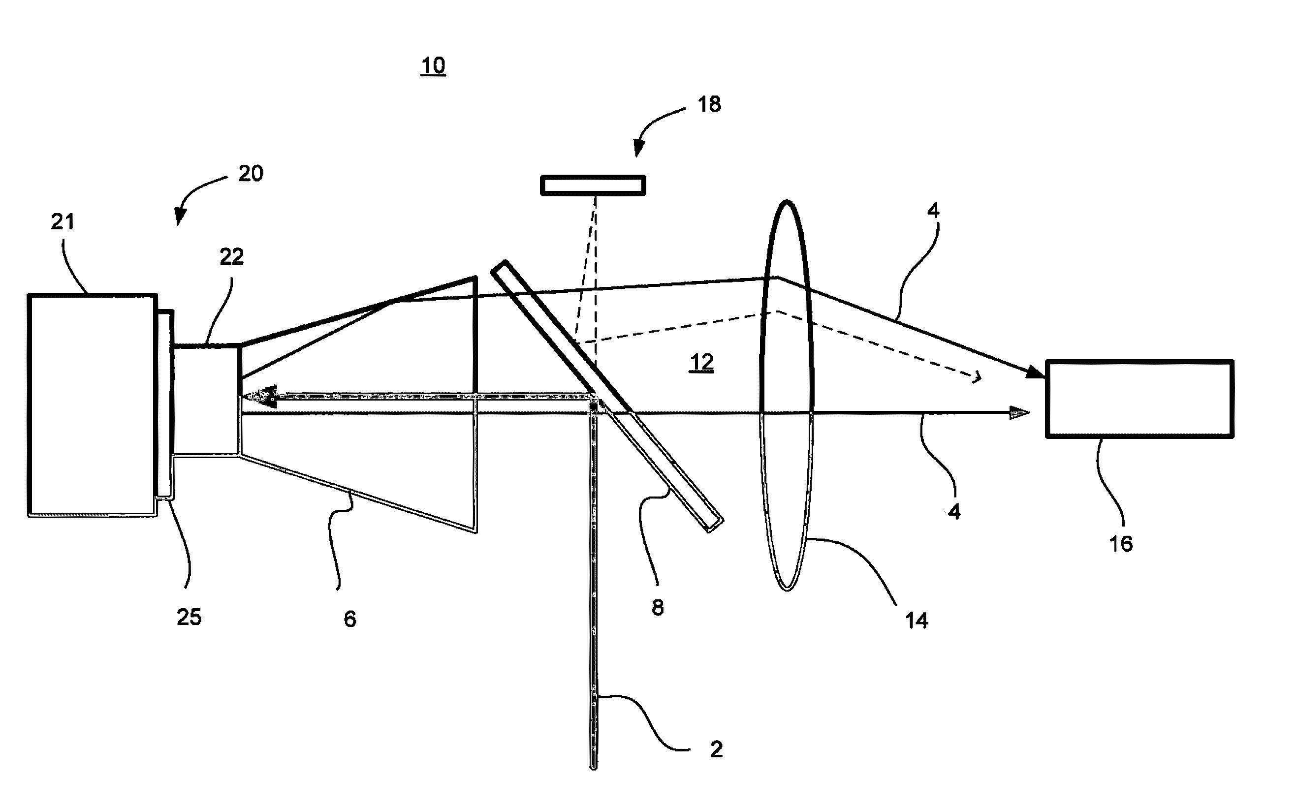
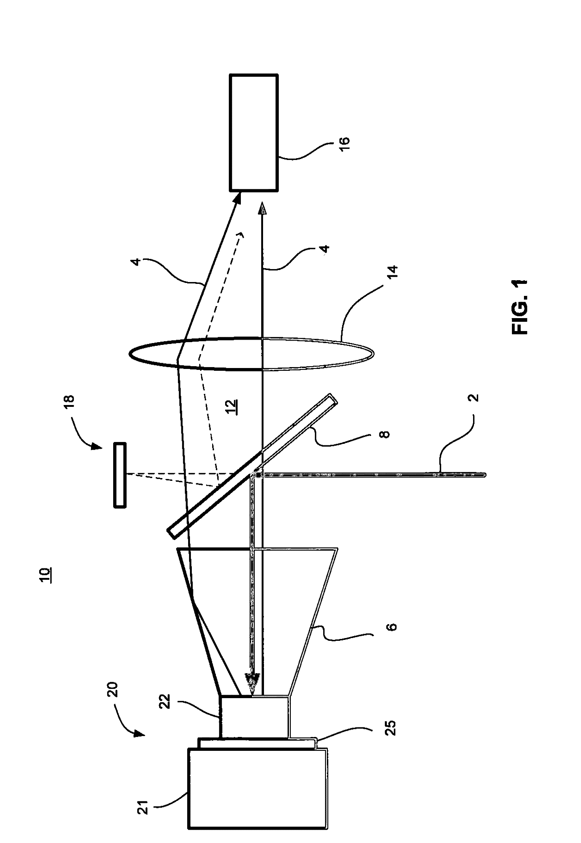
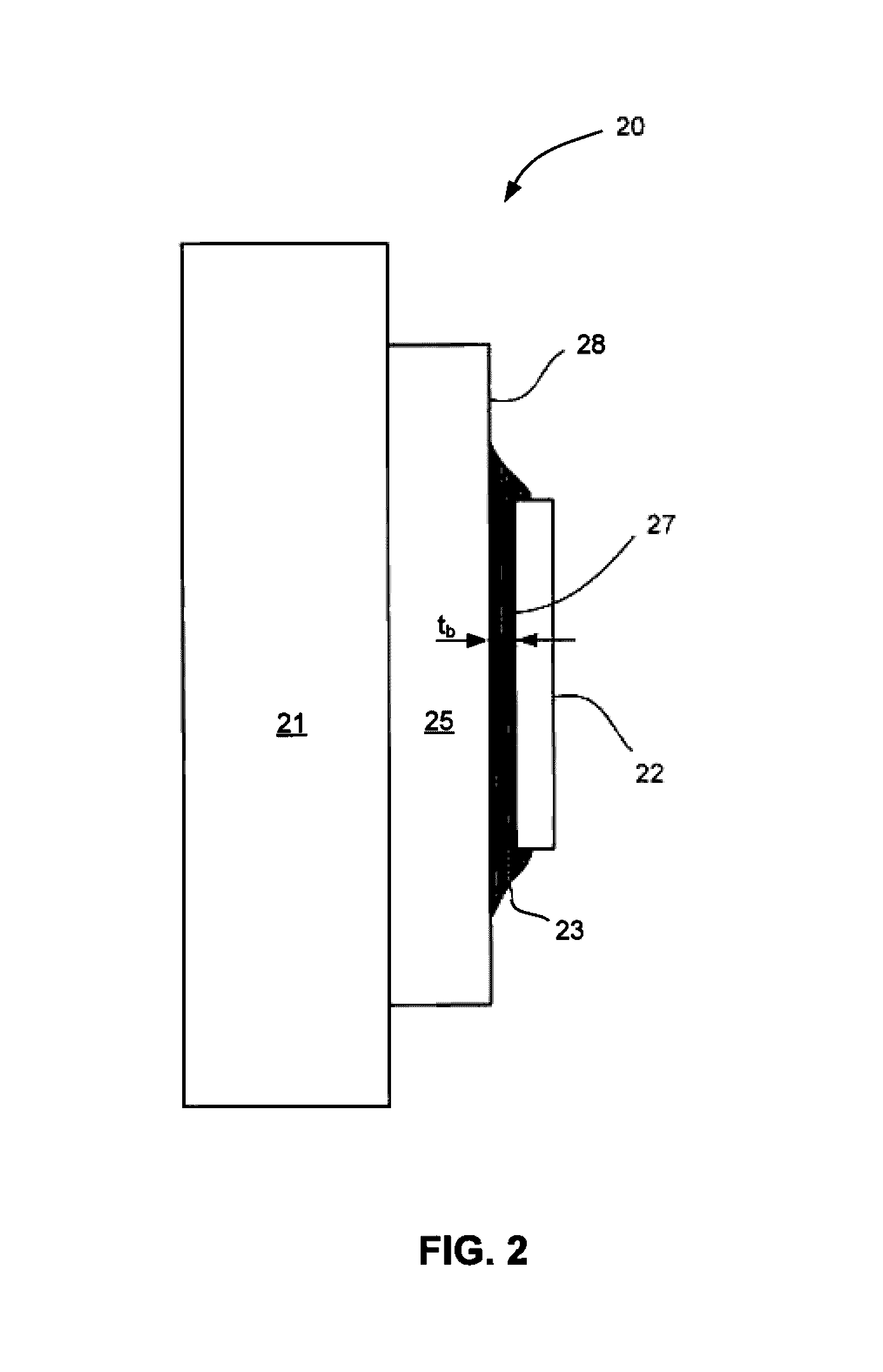
[0057]A Ce:YAG ceramic platelet, bonded to either enhance Al or Ag coated (and protected) Al substrates with ZnO-filled silicone glue provides a radiance of at least 1.0×10⁶ W / m2 / sr or an equivalent luminance of at least 5.0×10⁸ Cd / m2 and is particularly useful for laser intensities exceeding roughly 5×10⁶ W / m2. In the first embodiment, platelets are bonded with ZnO-filled silicone adhesive having a bond line that does not exceed 10 μm over the area defined by the pump light spot incident on the ceramic phosphor. Preferably, bond line thicknesses should be on the order of 5 μm or less. This can be accomplished with adhesives having thermal conductivities greater than about 0.4 W / m / K. Generally, the thermal conductance of the bond line should be at least 0.05 W / K, with greater than 0.1 W / K being most desirable.
[0058]The substrate must have a reflectance of at least 85%, preferably 95%, with >98% being most desirable. The lateral platelet dimensions are determined by the incident pump...
second embodiment
[0064]In the invention, the yellow emitting Ce:YAG ceramic phosphor is replaced with other luminescent ceramics known in the art. As an example, samples were made from three different Eu:nitride ceramic phosphors using standard methods. The data in FIG. 15 show the results of red and green emitting ceramic phosphor platelets bonded to Ag coated substrates with ZnO-silicone. While the overall powers do not match those of the Ce:YAG, the red CaAlSiN3 and green SrSiON both reach the maximum 25 W pump power without rolling over.
third embodiment
[0065]In a third embodiment, the ZnO-filled silicone bonding adhesive is replaced by a silicone incorporating other fillers, including but not limited to cristobalite, quartz, aluminum oxide, zirconium oxide, and other fillers that have very low losses at the desired optical wavelengths. Other bonding agents might include filled epoxies or filled translucent thermo-plastics with thermal conductivities of 0.4 W / m / K or higher and low optical losses. In the case of filled thermo-plastics, the material is deposited on a heated substrate above the melting point, and the ceramic phosphor platelet is pressed into the molten material and then solidified. Again, it is preferred to minimize bond line thicknesses such that the effective thermal conductance of the interface is on the order of 0.1 W / K or more. Most of these materials however are not as robust as silicone in terms of aging in the presence of strong blue fluxes and high operating temperatures.
PUM
| Property | Measurement | Unit |
|---|---|---|
| thickness | aaaaa | aaaaa |
| thermal conductivity | aaaaa | aaaaa |
| reflectivity | aaaaa | aaaaa |
Abstract
Description
Claims
Application Information
 - R&D
- Intellectual Property
- Life Sciences
- Materials
- Tech Scout
- Unparalleled Data Quality
- Higher Quality Content
- 60% Fewer Hallucinations
Browse by: Latest US Patents, China's latest patents, Technical Efficacy Thesaurus, Application Domain, Technology Topic, Popular Technical Reports.
© 2025 PatSnap. All rights reserved.Legal|Privacy policy|Modern Slavery Act Transparency Statement|Sitemap|About US| Contact US: help@patsnap.com


