Broadband Tunable External-Cavity Laser Using Small Mems Mirror

Active Publication Date: 2017-01-26
ACCELINK TECHNOLOGIES CO LTD
View PDF10 Cites 4 Cited by
  • Summary
  • Abstract
  • Description
  • Claims
  • Application Information

AI Technical Summary

Benefits of technology

The invention provides a multi-channel tunable external-cavity laser that uses micro-optical devices to realize a compact package structure. The laser uses a nanoscale grating to solve the spectral resolution precision problem and a MEMS rotating mirror for high-speed driving. The device also adapts to different environments and ensures long-term stability and reliability. The invention allows for precise wavelength tuning and stable lasering conditions. It uses a special etalon for precise wavelength tuning and to form a flexible grid filter. The invention has advantages such as using a non-zero level high-efficient diffraction grating, small cantilever beam type of MEMS reflecting mirror, and a special lens structure. Overall, the invention miniaturizes the Littman laser and enhances its vibration adaptability.

Problems solved by technology

However, applications of the coherent optical communication system with a rate of over 100 Gb / s raised higher demands for multi-channel tunable laser, that is, it required tunable laser with narrow linewidth feature, because system characteristics are restricted by signal phase noise.
However, heat is a physical quantity that is hard to be controlled precisely.
Thus thermo-optical tuning needs high-precision temperature calibration, and the thermal relaxation occurred during the tuning process often affects the tuning speed and control precision of the device.
However, due to the intrinsic structure and tuning demands of these lasers, it is difficult to adapt to the requirements of optical communication system for small volume, long-term stability and reliability.
Key problem therein is volume of the device.
However, reflecting mirror and electrostatic driving machine thereof are not in a same plane, so this kind of MEMS mechanism appears too enormous and complicated, with low yield, high production cost and relatively poor environmental adaptability.

Method used


Image

  • Broadband Tunable External-Cavity Laser Using Small Mems Mirror
  • Broadband Tunable External-Cavity Laser Using Small Mems Mirror
  • Broadband Tunable External-Cavity Laser Using Small Mems Mirror

Examples


Embodiment Construction

[0045]It is provided further detailed description thereof by using figures and specific embodiment to explain the principle of the invention.

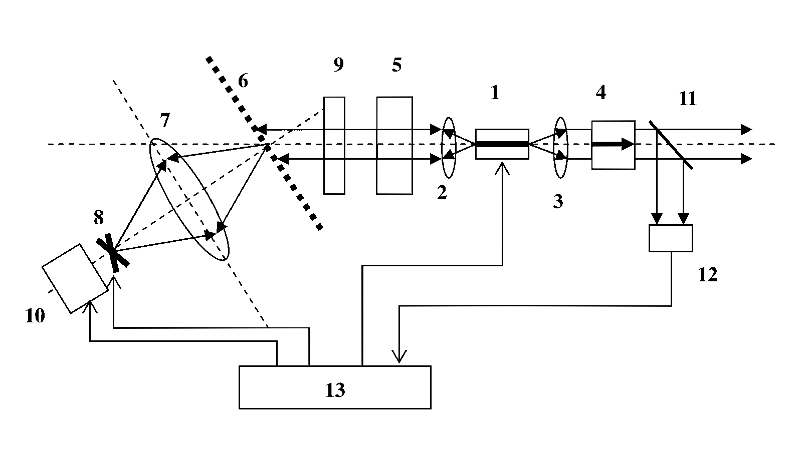
[0046]The structure of the broadband tunable external-cavity laser according to an embodiment of the invention is shown in FIG. 1, which mainly comprises a semiconductor optical gain device 1, a first and a second beam collimating lenses 2 and 3, an optical isolator 4, a grid filter 5 (optional), a grating 6, a convergent lens 7 (optional), a MEMS reflecting mirror 8, a temperature-phase compensator 9 (optional), a micro-shifter 10 (optional), a beam splitter 11 (optional), a photodetector 12 (optional) and a driving controller 13. It constitutes a kind of external-cavity semiconductor laser with small-size and large tuning range.

[0047]Specifically, the broadband tunable external-cavity laser comprises a micro-shifter 10, a MEMS reflecting mirror 8, a grating 6, a first beam collimating lens 2, a semiconductor optical gain device 1, a second be...


PUM


Abstract

A Raman pump laser control apparatus comprises a wavelength division multiplexer, a tap coupler, a photoelectric detector, an analogue amplification processing circuit, an analogue-to-digital converter, a fast Raman pump control unit, an digital-analog converter, and a Raman pump laser. The fast Raman pump control unit, after having known anticipated output light power of the Raman pump laser, based on a direct relationship between a current anticipated output light power of the Raman pump laser and input digital quantity that is needed by the digital-analog converter, uses a feedforward control mechanism so that actual output light power of the Raman pump laser fastly approximates the anticipated output light power thereof, and then synchronously combines with a feedback control mechanism so that the actual output light power of the Raman pump laser is precisely locked on the anticipated output light power, thereby achieving fast and precise control of the Raman pump laser.

Description

TECHNICAL FIELD[0001]Embodiments of this invention relate to solutions of tunable laser, especially to a broadband tunable external-cavity laser with grating and MEMS mirror. The laser can be applied to DWDM optical communication system.BACKGROUND[0002]Multi-channel tunable laser has been focus in the industry in recent years. Tunable laser products have been widely used in 10 Gb / s and 40 Gb / s optical communication system. These applications mainly use multi-channel tunable laser product with semiconductor integration technology (SGDBR). However, applications of the coherent optical communication system with a rate of over 100 Gb / s raised higher demands for multi-channel tunable laser, that is, it required tunable laser with narrow linewidth feature, because system characteristics are restricted by signal phase noise. Therefore, external-cavity laser with great linewidth control ability is becoming popular, in terms of applications of the coherent optical communication system with a...

Claims


Application Information

Patent Timeline
IPC IPC(8): H01S5/14H01S5/0683H01S3/08H01S3/105H01S5/068H01S3/102
CPCH01S5/143H01S5/068H01S5/0683H01S3/08086H01S3/105H01S3/102H01S5/141
Inventor FU, YANFENGLUO, YONGZHANG, DITANG, XUESHENGQIAN, KUNTANG, YIHU, SHENGLEIHU, QIANGGAO
Owner ACCELINK TECHNOLOGIES CO LTD
Why Eureka
Try Eureka