Eureka AIR delivers breakthrough ideas for toughest innovation challenges, trusted by R&D personnel around the world.

Lead-free high reliability solder alloys

a solder alloy, high reliability technology, applied in the field of solder alloys, can solve the problems of poor creep resistance of traditional lead-free sn—ag—cu (sac) alloys in harsh service environments, and reduced reliability of solder joints, etc., to achieve better mechanical properties, reduce melting temperature, and improve the effect of mechanical properties

Active Publication Date: 2017-03-09
AIM METALS & ALLOYS INC
View PDF2 Cites 13 Cited by
  • Summary
  • Abstract
  • Description
  • Claims
  • Application Information

AI Technical Summary

Benefits of technology

This patent describes a new type of solder that solves problems by being lead-free and having better mechanical properties, resistance to high temperatures, and reasonable wetting and spreading performance. It is made up of a combination of copper and either silver or tin.

Problems solved by technology

Moreover, high reliability harsh environment electronics are now being forced to change to lead free solder alloys due to commercial issues related to material supply of board finishes, component finishes that are lead free.
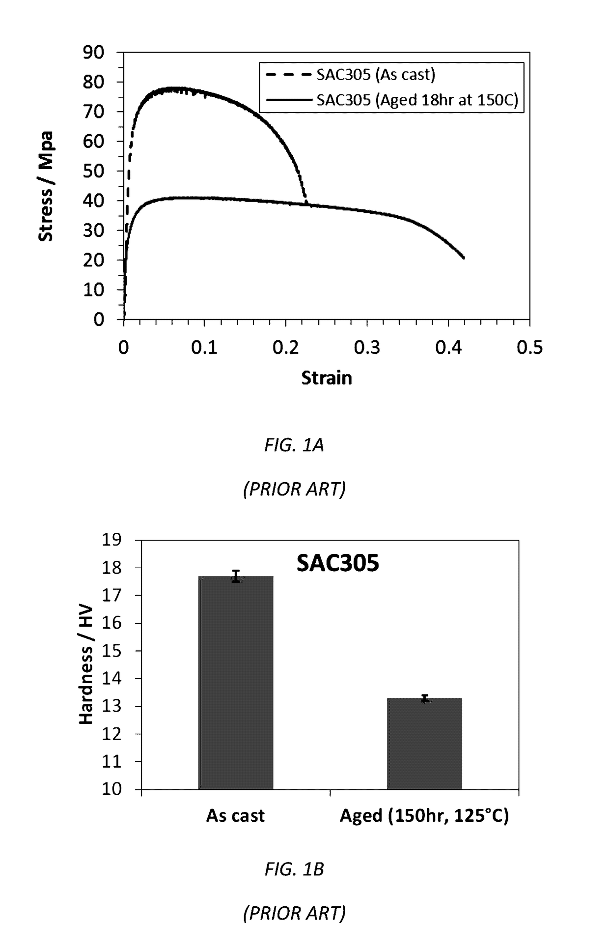
The traditional lead-free Sn—Ag—Cu (SAC) alloys have poor creep resistance in harsh service environments.
Such a degradation of mechanical strength represents a significant problem for solder joint reliability.
The relatively high silver content of SAC305 as well as fairly high undercooling temperature range leads to the formation of large Ag3Sn platelets which gives rise to poor mechanical performance.
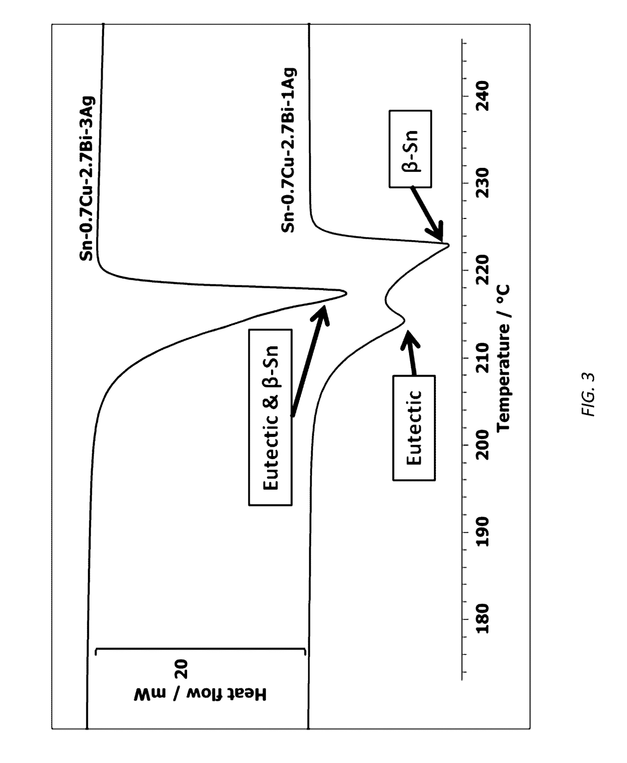
High undercooling of SAC alloys is associated with the difficulty of nucleating Sn solidification as a pro-eutectic phase.
Thus, during cooling the high undercooling of the joints can promote formation of undesirable pro-eutectic intermetallic phases, particularly Ag3Sn blade-like phase, that tend to coarsen drastically making the as-solidified solder joints brittle.

Method used


Image

  • Lead-free high reliability solder alloys
  • Lead-free high reliability solder alloys
  • Lead-free high reliability solder alloys

Examples


Embodiment Construction

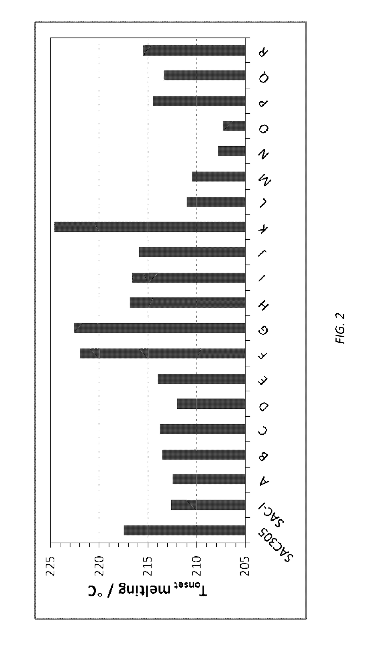
[0038]As described above The object of the invention consists of identifying a lead-free solder alloy based on the Sn—Cu (reference to Sn-0.7Cu) and Sn—Ag—Cu (reference to SAC305) systems which exhibits a comparatively lower melting temperature, better mechanical properties and high temperature creep resistance with reasonable wetting and spreading performance.

[0039]To achieve this object the following alloy compositions (Table 1) has been studied and fine-tuned:

TABLE 1Range of alloys composition studied.ElementsCuAgBiSbNiTi, Ga, Zn, InSnWt %0-3.50-3.80-5.60-7.50-0.20-0.15Bal.

[0040]Ni may increase strength through precipitation strengthening mechanism by forming intermetallic phases with Sn. Adding Ni increases the thermal stability of an alloy due to its high melting temperature. It has also been reported to improve thermal fatigue strength. Whereas Ni-free intermetallic experiences a phase transformation around 186° C., addition of Ni stabilizes the intermetallic phase (Cu,Ni)6Sn5...


PUM

PropertyMeasurementUnit
Fractionaaaaaaaaaa
Fractionaaaaaaaaaa
Fractionaaaaaaaaaa

Abstract

A lead-free, tin-based solder alloy contains about 0.6 to about 0.8 wt % copper, about 2.8 to about 3.2 wt % silver, about 2.8 to about 3.2 wt % bismuth, about 0.5 to about 0.7 wt % antimony, about 0.04 to about 0.07 wt % nickel, and about 0.007 to about 0.015 wt % titanium, exhibits low melting temperature, narrow solidification range and undercooling, high hardness and ultimate tensile strength at room temperature and high temperature, good formability, superior reliability performance such as creep resistance at high temperature, improved thermal cycle fatigue resistance on leadless (BGA and QFN) surface mount devices, stable microstructure at high temperature, very good solderability performance, low voiding in bottom terminated components, and mitigated tin whisker growth as compared with other lead-free solder alloys

Description

CROSS-REFERENCE TO RELATED APPLICATION[0001]This application claims priority to earlier filed U.S. Provisional Application Ser. No. 62 / 213,893, filed Sep. 3, 2015, the contents of which are incorporated herein by reference.BACKGROUND OF THE INVENTION[0002]1. Field of the Invention[0003]The present patent document relates generally to solder alloys and more particularly to a lead-free solder alloy with high reliability under a demanding range of environments.[0004]2. Background of the Related Art[0005]The increasing demand for high reliability electronics drives the electronics industry to seek for solders that can tolerate temperature fluctuations between cold and hot extremes. Moreover, high reliability harsh environment electronics are now being forced to change to lead free solder alloys due to commercial issues related to material supply of board finishes, component finishes that are lead free. The traditional lead-free Sn—Ag—Cu (SAC) alloys have poor creep resistance in harsh s...

Claims


Application Information

Patent Timeline
IPC IPC(8): B23K35/26C22C13/00C22C13/02
CPCB23K35/262C22C13/00C22C13/02
Inventor MAALEKIAN, MEHRANSEELIG, KARL
Owner AIM METALS & ALLOYS INC
Why Eureka
Eureka Blog
Learn More